Page 3070 of 4500
Fig. 83: Identifying Power Window System
Courtesy of TOYOTA MOTOR SALES, U.S.A., INC.
COMPONENTS
Page 3072 of 4500

Before adjusting the door position for vehicles equipped with side airbags and curtain shield airbags, be
sure to disconnect the battery. After adjustment, inspect the SRS warning lamp, the side airbag system
and the curtain shield airbag system for normal operation (see DIAGNOSIS SYSTEM
). Then initialize
both systems (see INITIALIZATION
).
<00380056004800030057004b0048000300560044005000480003005300550052004600480047005800550048000300490052005500030057004b004800030035002b00030056004c0047004800030044005100470003002f002b00030056004c0047004800
1100030003[
The procedures listed below are for the LH side.
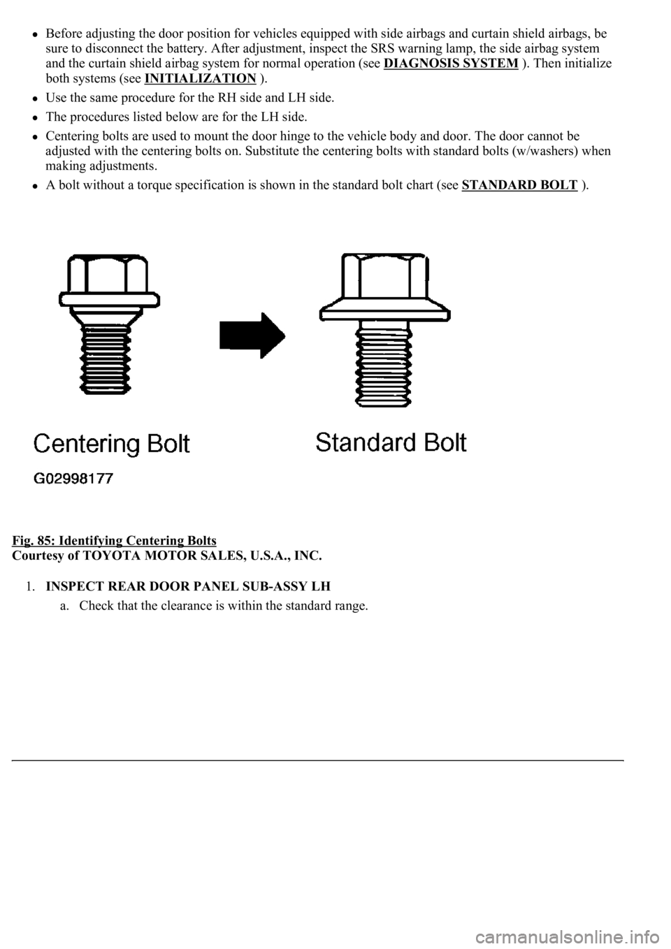
Centering bolts are used to mount the door hinge to the vehicle body and door. The door cannot be
adjusted with the centering bolts on. Substitute the centering bolts with standard bolts (w/washers) when
making adjustments.
A bolt without a torque specification is shown in the standard bolt chart (see STANDARD BOLT ).
Fig. 85: Identifying Centering Bolts
Courtesy of TOYOTA MOTOR SALES, U.S.A., INC.
1.INSPECT REAR DOOR PANEL SUB-ASSY LH
a. Check that the clearance is within the standard ran
ge.
Page 3127 of 4500
40.INITIALIZE POWER WINDOW SYSTEM (See INITIALIZATION )
Fig. 138: Identifying Power Window System
Courtesy of TOYOTA MOTOR SALES, U.S.A., INC.
COMPONENTS
Page 3128 of 4500
Fig. 139: Identifying Luggage Compartment Door Components
Courtesy of TOYOTA MOTOR SALES, U.S.A., INC.
ADJUSTMENT
HINT:
Page 3129 of 4500
Centering bolts are used to mount the door hinge to the vehicle body and door. The door cannot be
adjusted with the centering bolts on. Substitute the centering bolts with standard bolts (w/washers) when
making adjustments.
A bolt without a torque specification is shown in the standard bolt chart (see STANDARD BOLT ).
Fig. 140: Identifying Centering Bolts
Courtesy of TOYOTA MOTOR SALES, U.S.A., INC.
1.INSPECT LUGGAGE COMPARTMENT DOOR PANEL SUB-ASSY
Fig. 141: Inspecting Luggage Compartment Door Panel Sub
-Assy
Page 3165 of 4500
Fig. 1: Identifying Components & Replacements Location of Engine Immobilizer System (W/Smart Key
System)
Courtesy of TOYOTA MOTOR SALES, U.S.A., INC.
Page 3166 of 4500

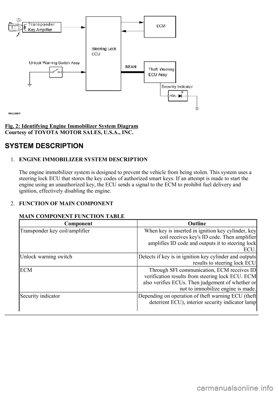
Fig. 2: Identifying Engine Immobilizer System Diagram
Courtesy of TOYOTA MOTOR SALES, U.S.A., INC.
1.ENGINE IMMOBILIZER SYSTEM DESCRIPTION
The engine immobilizer system is designed to prevent the vehicle from being stolen. This system uses a
steering lock ECU that stores the key codes of authorized smart keys. If an attempt is made to start the
engine using an unauthorized key, the ECU sends a signal to the ECM to prohibit fuel delivery and
ignition, effectively disabling the engine.
2.FUNCTION OF MAIN COMPONENT
MAIN COMPONENT FUNCTION TABLE
ComponentOutline
Transponder key coil/amplifierWhen key is inserted in ignition key cylinder, key
coil receives key's ID code. Then amplifier
amplifies ID code and outputs it to steering lock
ECU.
Unlock warning switchDetects if key is in ignition key cylinder and outputs
results to steering lock ECU
ECMThrough SFI communication, ECM receives ID
verification results from steering lock ECU. ECM
also verifies ECUs. Then judgement of whether or
not to immobilize engine is made.
Security indicatorDepending on operation of theft warning ECU (theft
deterrent ECU), interior security indicator lamp
Page 3169 of 4500
Fig. 3: Identifying Customer Problem Analysis Check Sheet
Courtesy of TOYOTA MOTOR SALES, U.S.A., INC.
HINT:
The key has 3 codes: the key code (immobilizer code), the smart code and wireless code. All of these code types
need to be registered. Refer to REGISTRATION
for the smart code (wireless code) registration procedures.
1.DESCRIPTION OF CODE REGISTRATION