Page 2036 of 4500

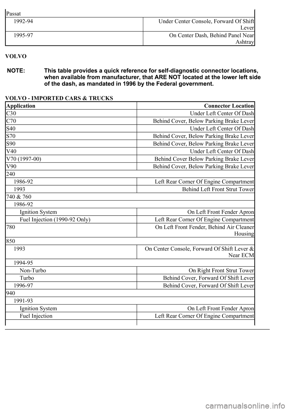
VOLVO
VOLVO - IMPORTED CARS & TRUCKS
Passat
1992-94Under Center Console, Forward Of Shift
Lever
1995-97On Center Dash, Behind Panel Near
Ashtray
ApplicationConnector Location
C30Under Left Center Of Dash
C70Behind Cover, Below Parking Brake Lever
S40Under Left Center Of Dash
S70Behind Cover, Below Parking Brake Lever
S90Behind Cover, Below Parking Brake Lever
V40Under Left Center Of Dash
V70 (1997-00)Behind Cover Below Parking Brake Lever
V90Behind Cover, Below Parking Brake Lever
240
1986-92Left Rear Corner Of Engine Compartment
1993Behind Left Front Strut Tower
740 & 760
1986-92
Ignition SystemOn Left Front Fender Apron
Fuel Injection (1990-92 Only)Left Rear Corner Of Engine Compartment
780On Left Front Fender, Behind Air Cleaner
Housing
850
1993On Center Console, Forward Of Shift Lever &
Near ECM
1994-95
Non-TurboOn Right Front Strut Tower
TurboBehind Cover, Forward Of Shift Lever
1996-97Behind Cover, Forward Of Shift Lever
940
1991-93
Ignition SystemOn Left Front Fender Apron
Fuel InjectionLeft Rear Corner Of Engine Compartment
Page 2196 of 4500

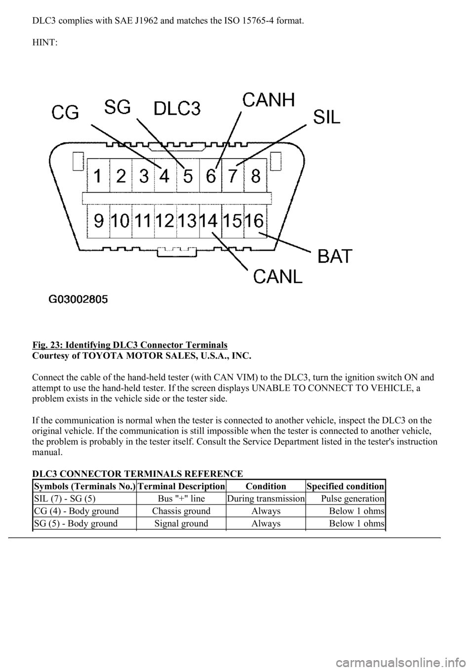
DLC3 complies with SAE J1962 and matches the ISO 15765-4 format.
HINT:
Fig. 23: Identifying DLC3 Connector Terminals
Courtesy of TOYOTA MOTOR SALES, U.S.A., INC.
Connect the cable of the hand-held tester (with CAN VIM) to the DLC3, turn the ignition switch ON and
attempt to use the hand-held tester. If the screen displays UNABLE TO CONNECT TO VEHICLE, a
problem exists in the vehicle side or the tester side.
If the communication is normal when the tester is connected to another vehicle, inspect the DLC3 on the
original vehicle. If the communication is still impossible when the tester is connected to another vehicle,
the problem is probably in the tester itself. Consult the Service Department listed in the tester's instruction
manual.
DLC3 CONNECTOR TERMINALS REFERENCE
Symbols (Terminals No.)Terminal DescriptionConditionSpecified condition
SIL (7) - SG (5)Bus "+" lineDuring transmissionPulse generation
CG (4) - Body groundChassis groundAlwaysBelow 1 ohms
SG (5) - Body groundSignal groundAlwaysBelow 1 ohms
Page 2197 of 4500
3.INSPECT BATTERY VOLTAGE
Standard: 11 to 14 V
If voltage is below 11 V, recharge the battery before proceeding.
1.CHECK DTC
a. Connect the hand-held tester to the Controller Area Network Vehicle Interface Module (CAN
VIM). Then connect the CAN VIM to the DLC3.
b. Turn the ignition switch ON.
c. Read DTCs on the tester screen.
HINT:
Refer to the hand-held tester operator's manual for further details.
Fig. 24: Connecting Hand
-Held Tester To DLC3
BAT (16) - Body groundBattery positiveAlways11 to 14 V
Page 2198 of 4500

Courtesy of TOYOTA MOTOR SALES, U.S.A., INC.
2.CLEAR DTC
a. Connect the hand-held tester to the Controller Area Network Vehicle Interface Module (CAN
VIM). Then connect the CAN VIM to the DLC3.
b. Turn the ignition switch ON.
c. Erase the DTCs by following the prompts on the tester screen.
HINT:
Refer to the hand-held tester operator's manual for further details.
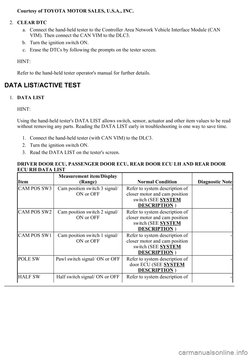
1.DATA LIST
HINT:
Using the hand-held tester's DATA LIST allows switch, sensor, actuator and other item values to be read
without removing any parts. Reading the DATA LIST early in troubleshooting is one way to save time.
1. Connect the hand-held tester (with CAN VIM) to the DLC3.
2. Turn the ignition switch ON.
3. Read the DATA LIST on the tester's screen.
DRIVER DOOR ECU, PASSENGER DOOR ECU, REAR DOOR ECU LH AND REAR DOOR
ECU RH DATA LIST
Item
Measurement item/Display
(Range)
Normal ConditionDiagnostic Note
CAM POS SW3Cam position switch 3 signal/
ON or OFFRefer to system description of
closer motor and cam position
switch (SEE SYSTEM
DESCRIPTION )
-
CAM POS SW2Cam position switch 2 signal/
ON or OFFRefer to system description of
closer motor and cam position
switch (SEE SYSTEM
DESCRIPTION )
-
CAM POS SW1Cam position switch 1 signal/
ON or OFFRefer to system description of
closer motor and cam position
switch (SEE SYSTEM
DESCRIPTION )
-
POLE SWPawl switch signal/ ON or OFFRefer to system description of
door ECU (SEE SYSTEM
DESCRIPTION )
-
HALF SWHalf switch signal/ ON or OFFRefer to system description of -
Page 2214 of 4500
b. Measure the voltage and resistance of the wire harness side connector.
Fig. 44: Checking Wire Harness (Driver Door ECU
- Body Ground)
Courtesy of TOYOTA MOTOR SALES, U.S.A., INC.
TERMINALS VOLTAGE AND RESISTANCE REFERENCE
NG: REPAIR OR REPLACE HARNESS AND CONNECTOR
OK: PROCEED TO NEXT CIRCUIT INSPECTION SHOWN ON PROBLEM SYMPTOMS
TABLE
CIRCUIT DESCRIPTION
Tester ConnectionConditionSpecified Condition
D25-1 (GND) - Body groundAlwaysBelow 1 ohms
D25-4 (CPUB) - Body groundAlways10 to 14 V
D25-6 (BDR) - Body groundAlways10 to 14 V
D25-5 (SIG) Body groundIgnition switch ON10 to 14 V
Page 2217 of 4500
NG: REPLACE RELAY
OK: Go to Next Step.
3.CHECK WIRE HARNESS (PASSENGER DOOR ECU - BATTERY AND BODY GROUND)
a. Disconnect the F17 ECU connector.
b. Measure the voltage and resistance of the wire harness side connector.
<0029004c004a001100030017001a001d00030026004b00480046004e004c0051004a0003003a004c005500480003002b0044005500510048005600560003000b003300440056005600480051004a0048005500030027005200520055000300280026003800
03[
- Body Ground)
Courtesy of TOYOTA MOTOR SALES, U.S.A., INC.
TERMINALS VOLTAGE AND RESISTANCE REFERENCE
3 - 5Below 1 ohms (when battery voltage is applied to terminals 1 and 2)
Tester ConnectionConditionSpecified Condition
F17-1 (GND) - Body groundAlwaysBelow 1 ohms
F17-4 (CPUB) - Body groundAlways10 to 14 V
F17-6 (BDR) - Body groundAlways10 to 14 V
F17-5 (SIG) Body groundIgnition switch ON10 to 14 V
Page 2221 of 4500
OK: Go to Next Step.
3.CHECK WIRE HARNESS (REAR DOOR LH ECU - BATTERY AND BODY GROUND)
a. Disconnect the R13 ECU connector.
b. Measure the voltage and resistance of the wire harness side connector.
Fig. 50: Checking Wire Harness (Rear Door LH ECU
- Body Ground)
Courtesy of TOYOTA MOTOR SALES, U.S.A., INC.
TERMINALS RESISTANCE AND VOLTAGE REFERENCE
NG: REPAIR OR REPLACE HARNESS AND CONNECTOR
OK: PROCEED TO NEXT CIRCUIT INSPECTION SHOWN ON PROBLEM SYMPTOMS
TABLE
Tester ConnectionConditionSpecified Condition
R13-6 (GND) - Body groundAlwaysBelow 1 ohms
R13-1 (CPUB) - Body groundAlways10 to 14 V
R13-2 (BDR) - Body groundAlways10 to 14 V
R13-26 (SIG) Body groundIgnition switch ON10 to 14 V
Page 2225 of 4500
NG: REPAIR OR REPLACE HARNESS AND CONNECTOR
OK: PROCEED TO NEXT CIRCUIT INSPECTION SHOWN ON PROBLEM SYMPTOMS
TABLE
CIRCUIT DESCRIPTION
The door lock assembly has a built-in closer position switch, which detects the position of the closer.
WIRING DIAGRAM
Fig. 54: Door Closer Position Switch Circuit On Driver Side Door
- Wiring Diagram
Courtesy of TOYOTA MOTOR SALES, U.S.A., INC.
INSPECTION PROCEDURE
1.READ VALUE OF DATA LIST (DOOR CLOSER POSITION SWITCH (POLE/HALF/ FULL))
a. Check the DATA LIST for proper functioning of the door closer position switch.
DRIVER DOOR EC
R14-1 (CPUB) - Body groundAlways10 to 14 V
R14-2 (BDR) - Body groundAlways10 to 14 V
R14-26 (SIG) Body groundIgnition switch ON10 to 14 V
Measurement item / Display