Page 2520 of 4500

OK: Go To Next Step.
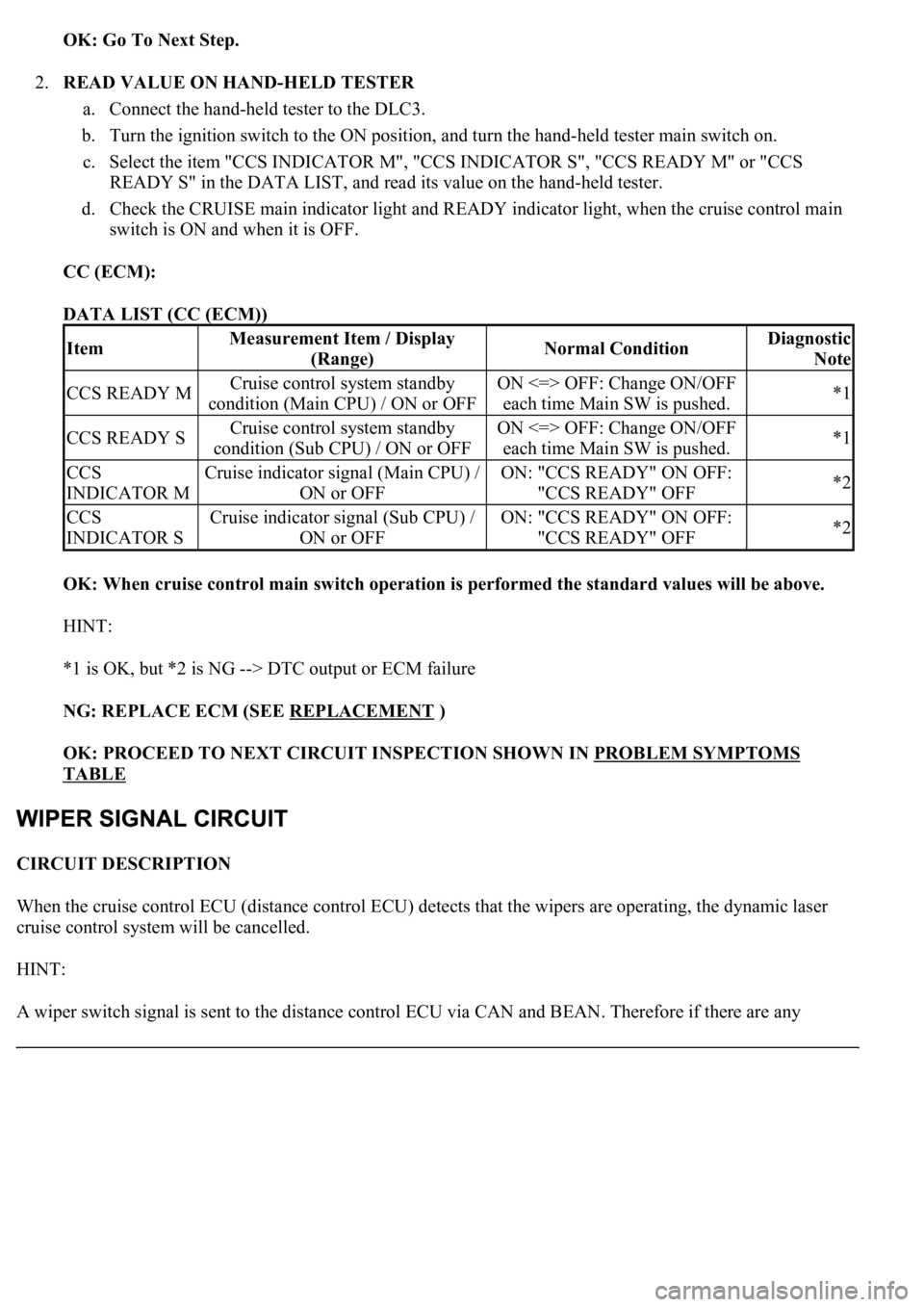
2.READ VALUE ON HAND-HELD TESTER
a. Connect the hand-held tester to the DLC3.
b. Turn the ignition switch to the ON position, and turn the hand-held tester main switch on.
c. Select the item "CCS INDICATOR M", "CCS INDICATOR S", "CCS READY M" or "CCS
READY S" in the DATA LIST, and read its value on the hand-held tester.
d. Check the CRUISE main indicator light and READY indicator light, when the cruise control main
switch is ON and when it is OFF.
CC (ECM):
DATA LIST (CC (ECM))
OK: When cruise control main switch operation is performed the standard values will be above.
HINT:
*1 is OK, but *2 is NG --> DTC output or ECM failure
NG: REPLACE ECM (SEE REPLACEMENT
)
OK: PROCEED TO NEXT CIRCUIT INSPECTION SHOWN IN PROBLEM SYMPTOMS
TABLE
CIRCUIT DESCRIPTION
When the cruise control ECU (distance control ECU) detects that the wipers are operating, the dynamic laser
cruise control system will be cancelled.
HINT:
A wiper switch si
gnal is sent to the distance control ECU via CAN and BEAN. Therefore if there are any
ItemMeasurement Item / Display
(Range)Normal ConditionDiagnostic
Note
CCS READY MCruise control system standby
condition (Main CPU) / ON or OFFON <=> OFF: Change ON/OFF
each time Main SW is pushed.*1
CCS READY SCruise control system standby
condition (Sub CPU) / ON or OFFON <=> OFF: Change ON/OFF
each time Main SW is pushed.*1
CCS
INDICATOR MCruise indicator signal (Main CPU) /
ON or OFFON: "CCS READY" ON OFF:
"CCS READY" OFF*2
CCS
INDICATOR SCruise indicator signal (Sub CPU) /
ON or OFFON: "CCS READY" ON OFF:
"CCS READY" OFF*2
Page 2547 of 4500
Fig. 15: Identifying Cruise Control Main Switch
Courtesy of TOYOTA MOTOR SALES, U.S.A., INC.
2.INSPECT MODE SWITCH
a. Turn the ignition switch to the ON position.
HINT:
Dynamic radar cruise system is in the default mode.
b. After pushing the ON-OFF button on, push the cruise control main switch to MODE for at least 1
second without any other control. Make sure that only "NORM." and nothing else is indicated on
the display.
Page 2549 of 4500
Fig. 17: [Display NORM]
Courtesy of TOYOTA MOTOR SALES, U.S.A., INC.
3.INSPECT STEERING PAD SWITCH ASSY
a. Turn the ignition switch to the ON position.
b. Push on the ON-OFF button of the cruise control main switch.
c. Push on the distance control switch (DISP2) of the steering pad switch.
d. Check that the indication of vehicle-to-vehicle distance, which is shown in the multi-information
displa
y on the combination meter, changes from "LONG", "MIDDLE" to "SHORT" in that order.
Page 2552 of 4500
1.DISTANCE CONTROL ECU
Fig. 20: Identifying ECU Terminals
Courtesy of TOYOTA MOTOR SALES, U.S.A., INC.
ECU TERMINALS VOLTAGE AND RESISTANCE SPECIFICATION
Symbols (Terminals
No.)Wiring
ColorTerminal DescriptionConditionSpecified
Condition
+B - GND (D2-1 - D2-
12)R-B - BRBatteryAlways10 to 14V
CANH (D2 - 8)LGCAN communication
signalCAN
communication
circuit
-
CANL (D2 - 9)LCAN communication
signalCAN
communication
circuit
-
SGND - Body ground
(D2-10 - Body ground)BR - Body
groundGroundAlwaysBelow 1 ohms
GND - Body ground
(D2-12 - Body ground)BR - Body
groundGroundAlwaysBelow 1ohms
IGB - GND (D2-13 -
D2-12)L-0 - BRIgnition switch ON signalIgnition switch OFF
--> ONBelow 1 V --> 10
to 14V
LRDD - GND (D2-22 -
D2-12)P-L - BRMillimeter wave radar
sensor input signalIgnition switch ONPulse generation
(see waveform 1)
LRRD - GND (D2-23 -
D2-12)L-Y - BRMillimeter wave radar
sensor output signalIgnition switch ONPulse generation
(see waveform 2)
Page 2553 of 4500
a. Reference: waveform 1
HINT:
Terminal: LRDD - GND
Gauge set: 2 V/DIV, 10 ms/DIV
Condition: Ignition switch ON
Fig. 21: Signal Waveform Graph (Waveform 1)
Courtesy of TOYOTA MOTOR SALES, U.S.A., INC.
b. Reference: waveform 2
HINT:
Terminal: LRRD - GND
Gauge set: 2 V/DIV, 5 ms/DIV
Condition: Ignition switch ON
Page 2556 of 4500
Fig. 25: Identifying Millimeter Wave Radar Sensor Connector Terminals
Courtesy of TOYOTA MOTOR SALES, U.S.A., INC.
MILLIMETER WAVE RADAR SENSOR CONNECTOR TERMINALS VOLTAGE AND
RESISTANCE SPECIFICATION
a. Reference: waveform 1
HINT:
Terminal: LRDD - SGND
Symbols (Terminal No.)Wiring
ColorTerminal DescriptionConditionSpecified Condition
LGND - Body ground
(M7-1 - Body ground)B-L -Body
groundGround (Distance signal)AlwaysBelow 1 ohms
SGND - Body ground
(M7-2 - Body ground)B-R - Body
groundGroundAlwaysBelow 1 ohms
LRDD - SGND (M7-3 -
M7-2)B-O - B-RMillimeter wave radar
sensor output signalIgnition
switch ONPulse generation (see
waveform 1)
LRRD - SGND (M7-4 -
M7-2)B-Y - B-RMillimeter wave radar
sensor input signalIgnition
switch ONPulse generation (see
waveform 2)
IGB - SGND (M7-5 - M7-
2)B - B-RPower sourceIgnition
switch ON10 to 14V
Page 2557 of 4500
Gauge set: 1 V/DIV, 2 ms/DIV
Condition: Ignition switch ON
Fig. 26: Signal Waveform Graph (Waveform 1)
Courtesy of TOYOTA MOTOR SALES, U.S.A., INC.
b. Reference: waveform 2
HINT:
Terminal: LRRD - SGND
Gauge set: 1 V/DIV, 2 ms/DIV
Condition: Ignition switch ON
Page 2562 of 4500

tester to the DLC3, turned the ignition switch to the ON position and operated the tester, there is a
problem on either the vehicle side or the tool side.
If communication is normal when the tool is connected to another vehicle, inspect the DLC3 on the
original vehicle.
If communication is still impossible when the tool is connected to another vehicle, the problem is
probably in the tool itself, so consult the Service Department listed in the tool's instruction manual.
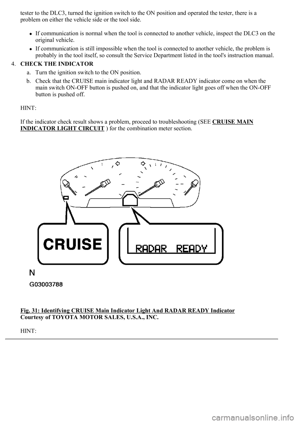
4.CHECK THE INDICATOR
a. Turn the ignition switch to the ON position.
b. Check that the CRUISE main indicator light and RADAR READY indicator come on when the
main switch ON-OFF button is pushed on, and that the indicator light goes off when the ON-OFF
button is pushed off.
HINT:
If the indicator check result shows a problem, proceed to troubleshooting (SEE CRUISE MAIN
INDICATOR LIGHT CIRCUIT ) for the combination meter section.
<0029004c004a0011000300160014001d0003002c0047004800510057004c0049005c004c0051004a0003002600350038002c00360028000300300044004c00510003002c00510047004c004600440057005200550003002f004c004a004b00570003002400
51004700030035002400270024003500030035002800240027[Y Indicator
Courtesy of TOYOTA MOTOR SALES, U.S.A., INC.
HINT: