Page 2463 of 4500
If a malfunction occurs in the vehicle speed sensors, the stop lamp switch, or other related parts during
cruise control driving, the ECU actuates AUTO CANCEL of the cruise control and blinks the CRUISE
main indicator light. This indicator light informs the driver of the malfunction. At the same time, the
malfunction is stored as a diagnostic trouble code.
Fig. 32: Identifying Blinking Pattern Of CRUISE Main Indicator Light
Courtesy of TOYOTA MOTOR SALES, U.S.A., INC.
1.DTC CHECK
a. Connect the hand-held tester to the DLC3.
b. Turn the ignition switch to the ON position.
c. Read the DTCs by following the prompts on the tester screen.
2.DTC CLEAR
a. Connect the hand-held tester to the DLC3.
b. Turn the ignition switch to the ON position.
c. Clear the DTCs following the prompts on the tester screen.
HINT:
Refer to the han
d-held tester operators manual for further details.
Page 2467 of 4500
Courtesy of TOYOTA MOTOR SALES, U.S.A., INC.
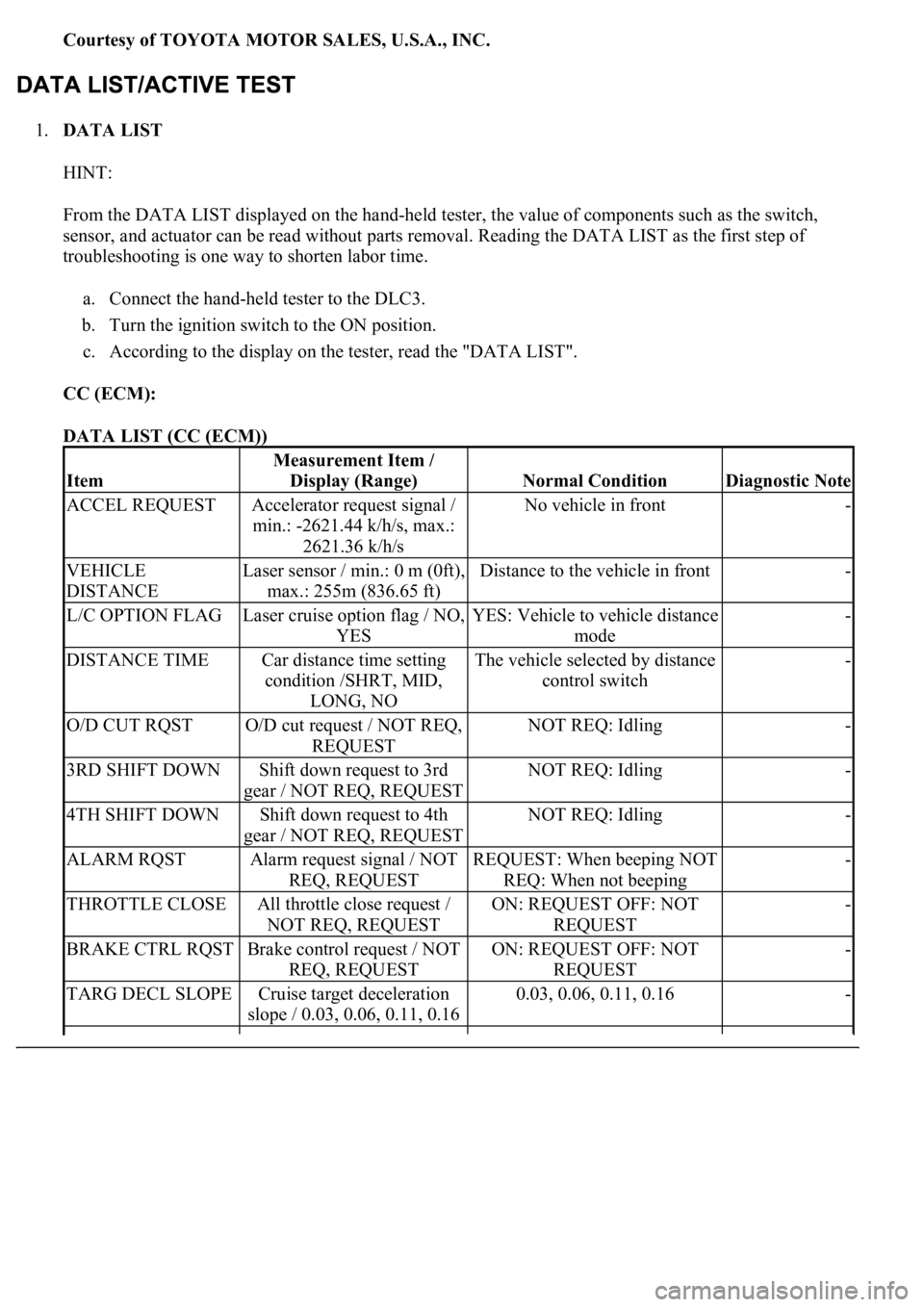
1.DATA LIST
HINT:
From the DATA LIST displayed on the hand-held tester, the value of components such as the switch,
sensor, and actuator can be read without parts removal. Reading the DATA LIST as the first step of
troubleshooting is one way to shorten labor time.
a. Connect the hand-held tester to the DLC3.
b. Turn the ignition switch to the ON position.
c. According to the display on the tester, read the "DATA LIST".
CC (ECM):
DATA LIST (CC (ECM))
Item
Measurement Item /
Display (Range)
Normal ConditionDiagnostic Note
ACCEL REQUESTAccelerator request signal /
min.: -2621.44 k/h/s, max.:
2621.36 k/h/sNo vehicle in front-
VEHICLE
DISTANCELaser sensor / min.: 0 m (0ft),
max.: 255m (836.65 ft)Distance to the vehicle in front-
L/C OPTION FLAGLaser cruise option flag / NO,
YESYES: Vehicle to vehicle distance
mode-
DISTANCE TIMECar distance time setting
condition /SHRT, MID,
LONG, NOThe vehicle selected by distance
control switch-
O/D CUT RQSTO/D cut request / NOT REQ,
REQUESTNOT REQ: Idling-
3RD SHIFT DOWNShift down request to 3rd
gear / NOT REQ, REQUESTNOT REQ: Idling-
4TH SHIFT DOWNShift down request to 4th
gear / NOT REQ, REQUESTNOT REQ: Idling-
ALARM RQSTAlarm request signal / NOT
REQ, REQUESTREQUEST: When beeping NOT
REQ: When not beeping-
THROTTLE CLOSEAll throttle close request /
NOT REQ, REQUESTON: REQUEST OFF: NOT
REQUEST-
BRAKE CTRL RQSTBrake control request / NOT
REQ, REQUESTON: REQUEST OFF: NOT
REQUEST-
TARG DECL SLOPECruise target deceleration
slope / 0.03, 0.06, 0.11, 0.160.03, 0.06, 0.11, 0.16-
Page 2469 of 4500
HINT:
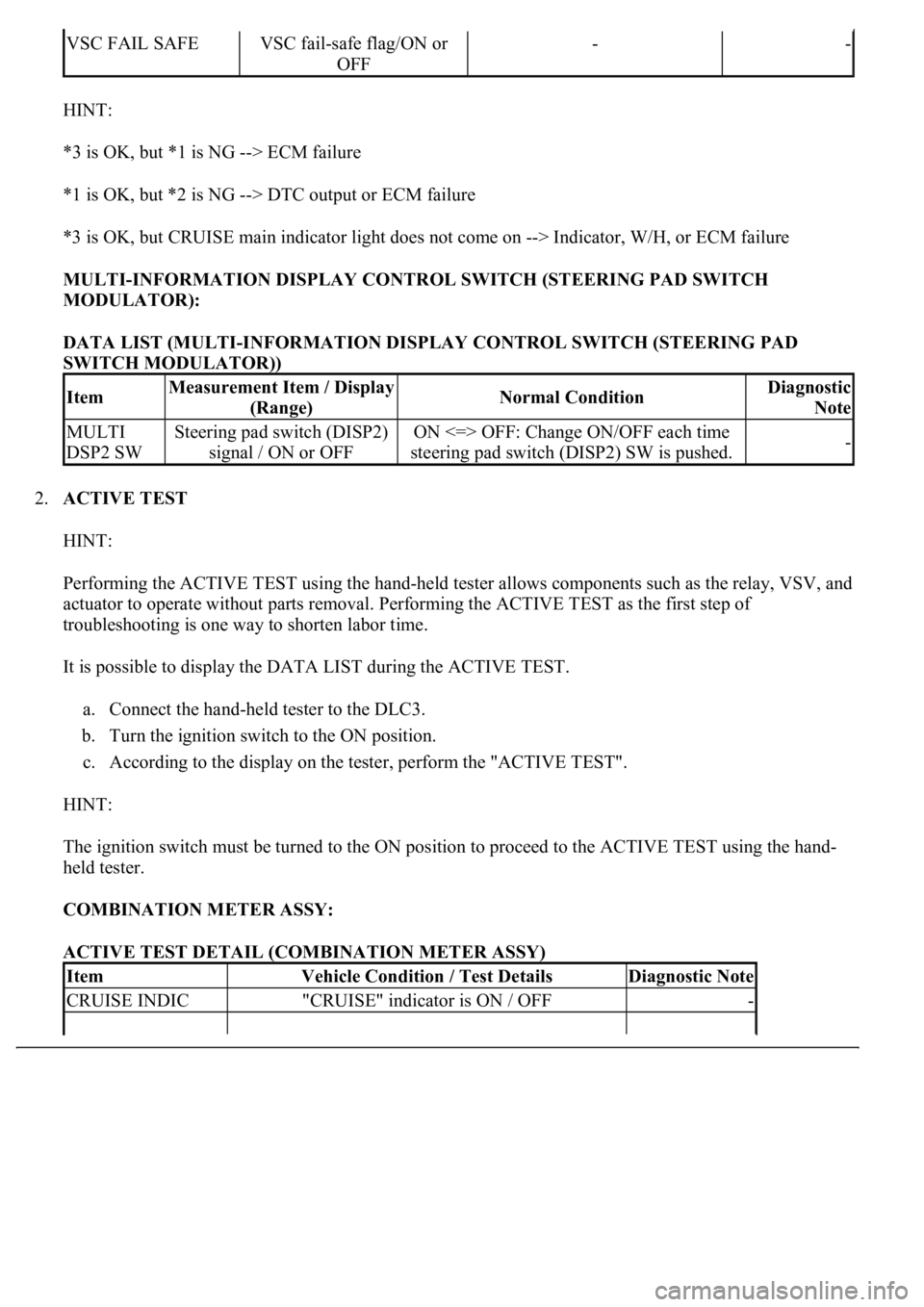
*3 is OK, but *1 is NG --> ECM failure
*1 is OK, but *2 is NG --> DTC output or ECM failure
*3 is OK, but CRUISE main indicator light does not come on --> Indicator, W/H, or ECM failure
MULTI-INFORMATION DISPLAY CONTROL SWITCH (STEERING PAD SWITCH
MODULATOR):
DATA LIST (MULTI-INFORMATION DISPLAY CONTROL SWITCH (STEERING PAD
SWITCH MODULATOR))
2.ACTIVE TEST
HINT:
Performing the ACTIVE TEST using the hand-held tester allows components such as the relay, VSV, and
actuator to operate without parts removal. Performing the ACTIVE TEST as the first step of
troubleshooting is one way to shorten labor time.
It is possible to display the DATA LIST during the ACTIVE TEST.
a. Connect the hand-held tester to the DLC3.
b. Turn the ignition switch to the ON position.
c. According to the display on the tester, perform the "ACTIVE TEST".
HINT:
The ignition switch must be turned to the ON position to proceed to the ACTIVE TEST using the hand-
held tester.
COMBINATION METER ASSY:
ACTIVE TEST DETAIL (COMBINATION METER ASSY)
VSC FAIL SAFEVSC fail-safe flag/ON or
OFF--
ItemMeasurement Item / Display
(Range)Normal ConditionDiagnostic
Note
MULTI
DSP2 SWSteering pad switch (DISP2)
signal / ON or OFFON <=> OFF: Change ON/OFF each time
steering pad switch (DISP2) SW is pushed.-
ItemVehicle Condition / Test DetailsDiagnostic Note
CRUISE INDIC"CRUISE" indicator is ON / OFF-
Page 2475 of 4500
b. Turn the ignition switch to the ON position, and turn the hand-held tester main switch on.
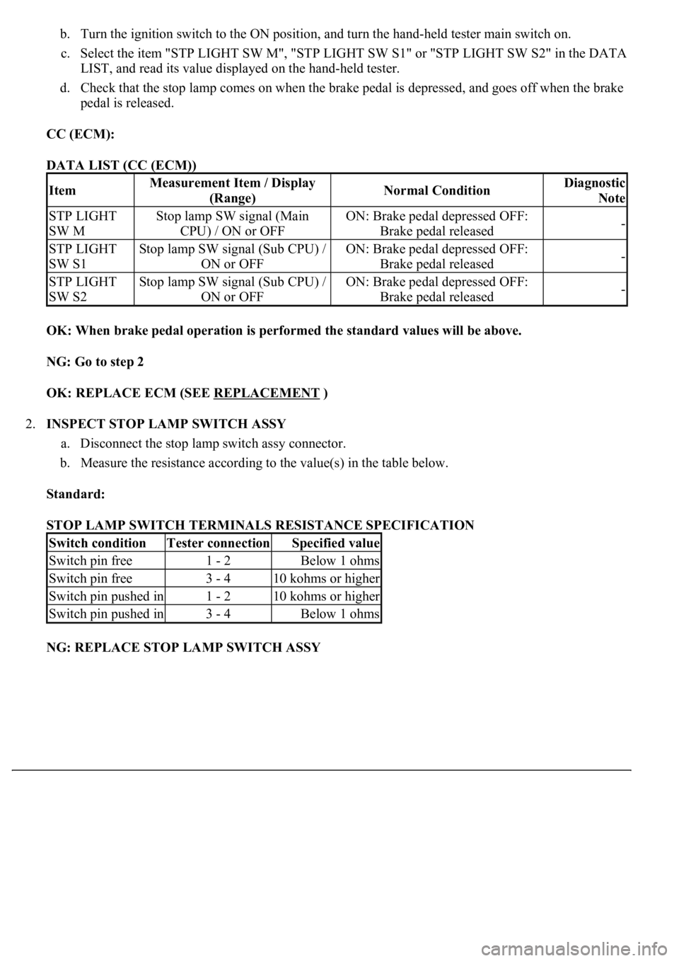
c. Select the item "STP LIGHT SW M", "STP LIGHT SW S1" or "STP LIGHT SW S2" in the DATA
LIST, and read its value displayed on the hand-held tester.
d. Check that the stop lamp comes on when the brake pedal is depressed, and goes off when the brake
pedal is released.
CC (ECM):
DATA LIST (CC (ECM))
OK: When brake pedal operation is performed the standard values will be above.
NG: Go to step 2
OK: REPLACE ECM (SEE REPLACEMENT
)
2.INSPECT STOP LAMP SWITCH ASSY
a. Disconnect the stop lamp switch assy connector.
b. Measure the resistance according to the value(s) in the table below.
Standard:
STOP LAMP SWITCH TERMINALS RESISTANCE SPECIFICATION
NG: REPLACE STOP LAMP SWITCH ASSY
ItemMeasurement Item / Display
(Range)Normal ConditionDiagnostic
Note
STP LIGHT
SW MStop lamp SW signal (Main
CPU) / ON or OFFON: Brake pedal depressed OFF:
Brake pedal released-
STP LIGHT
SW S1Stop lamp SW signal (Sub CPU) /
ON or OFFON: Brake pedal depressed OFF:
Brake pedal released-
STP LIGHT
SW S2Stop lamp SW signal (Sub CPU) /
ON or OFFON: Brake pedal depressed OFF:
Brake pedal released-
Switch conditionTester connectionSpecified value
Switch pin free1 - 2Below 1 ohms
Switch pin free3 - 410 kohms or higher
Switch pin pushed in1 - 210 kohms or higher
Switch pin pushed in3 - 4Below 1 ohms
Page 2476 of 4500
Fig. 45: Identifying Stop Lamp Switch Assy Connector
Courtesy of TOYOTA MOTOR SALES, U.S.A., INC.
OK: Go To Next Step.
3.CHECK HARNESS AND CONNECTOR (STOP LAMP SWITCH - BATTERY)
a. Measure the voltage according to the value(s) in the table below.
Standard:
STOP LAMP SWITCH TERMINALS VOLTAGE SPECIFICATION
Tester connectionConditionSpecified condition
S19-2 - Body groundAlways10 to 14 V
S19-3 - Body groundIgnition SW ON10 to 14 V
Page 2477 of 4500
Fig. 46: Identifying Stop Lamp Switch Assy Connector
Courtesy of TOYOTA MOTOR SALES, U.S.A., INC.
NG: REPAIR OR REPLACE HARNESS OR CONNECTOR
OK: Go To Next Step.
4.INSPECT ECM
a. Reconnect the stop lamp switch connector.
b. Disconnect the E2 and E3 connectors from the ECM.
c. Turn the ignition switch to the ON position.
d. Measure the voltage according to the value(s) in the table below.
Standard:
ECM TERMINALS VOLTAGE SPECIFICATION
Pedal conditionTester connectionSpecification
DepressedE2-4 (STP) - Body ground10 to 14 V
ReleasedE2-4 (STP) - Body groundBelow 1 V
Page 2482 of 4500
OK: REPLACE DRIVER SIDE J/B
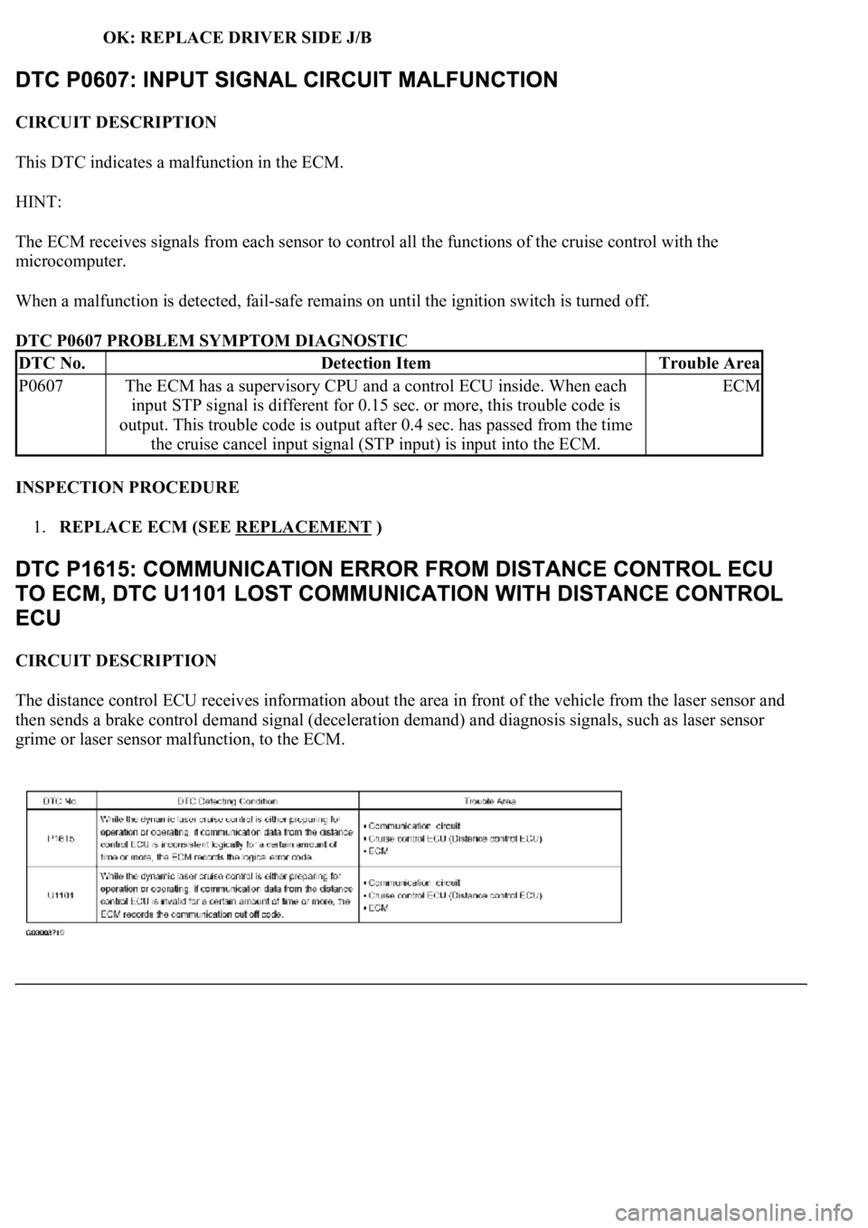
CIRCUIT DESCRIPTION
This DTC indicates a malfunction in the ECM.
HINT:
The ECM receives signals from each sensor to control all the functions of the cruise control with the
microcomputer.
When a malfunction is detected, fail-safe remains on until the ignition switch is turned off.
DTC P0607 PROBLEM SYMPTOM DIAGNOSTIC
INSPECTION PROCEDURE
1.REPLACE ECM (SEE REPLACEMENT
)
CIRCUIT DESCRIPTION
The distance control ECU receives information about the area in front of the vehicle from the laser sensor and
then sends a brake control demand signal (deceleration demand) and diagnosis signals, such as laser sensor
grime or laser sensor malfunction, to the ECM.
DTC No.Detection ItemTrouble Area
P0607The ECM has a supervisory CPU and a control ECU inside. When each
input STP signal is different for 0.15 sec. or more, this trouble code is
output. This trouble code is output after 0.4 sec. has passed from the time
the cruise cancel input signal (STP input) is input into the ECM.ECM
Page 2484 of 4500
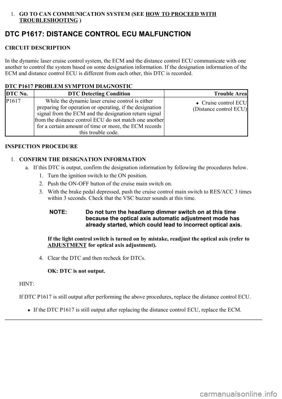
1.GO TO CAN COMMUNICATION SYSTEM (SEE HOW TO PROCEED WITH
TROUBLESHOOTING )
CIRCUIT DESCRIPTION
In the dynamic laser cruise control system, the ECM and the distance control ECU communicate with one
another to control the system based on some designation information. If the designation information of the
ECM and distance control ECU is different from each other, this DTC is recorded.
DTC P1617 PROBLEM SYMPTOM DIAGNOSTIC
INSPECTION PROCEDURE
1.CONFIRM THE DESIGNATION INFORMATION
a. If this DTC is output, confirm the designation information by following the procedures below.
1. Turn the ignition switch to the ON position.
2. Push the ON-OFF button of the cruise main switch on.
3. With the brake pedal depressed, push the cruise control main switch to RES/ACC 3 times
within 3 seconds. Check that the VSC buzzer sounds at this time.
If the light control switch is turned on by mistake, readjust the optical axis (refer to
ADJUSTMENT
for optical axis adjustment).
4. Clear the DTC and then recheck for DTCs.
OK: DTC is not output.
HINT:
If DTC P1617 is still output after performing the above procedures, replace the distance control ECU.
If the DTC P1617 is still output after replacing the distance control ECU, replace the ECM.
DTC No.DTC Detecting ConditionTrouble Area
P1617While the dynamic laser cruise control is either
<005300550048005300440055004c0051004a00030049005200550003005200530048005500440057004c005200510003005200550003005200530048005500440057004c0051004a000f0003004c004900030057004b00480003004700480056004c004a00
5100440057004c005200510003[
signal from the ECM and the designation return signal
from the distance control ECU do not match one another
for a certain amount of time or more, the ECM records
this trouble code.Cruise control ECU
(Distance control ECU)