Page 1995 of 4500
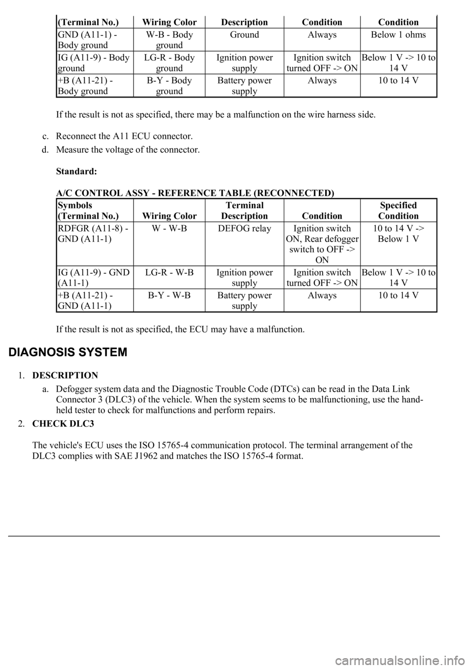
If the result is not as specified, there may be a malfunction on the wire harness side.
c. Reconnect the A11 ECU connector.
d. Measure the voltage of the connector.
Standard:
A/C CONTROL ASSY - REFERENCE TABLE (RECONNECTED)
If the result is not as specified, the ECU may have a malfunction.
1.DESCRIPTION
a. Defogger system data and the Diagnostic Trouble Code (DTCs) can be read in the Data Link
<002600520051005100480046005700520055000300160003000b0027002f00260016000c00030052004900030057004b0048000300590048004b004c0046004f004800110003003a004b0048005100030057004b004800030056005c005600570048005000
03005600480048005000560003005700520003004500480003[malfunctioning, use the hand-
held tester to check for malfunctions and perform repairs.
2.CHECK DLC3
The vehicle's ECU uses the ISO 15765-4 communication protocol. The terminal arrangement of the
DLC3 complies with SAE J1962 and matches the ISO 15765-4 format.
(Terminal No.)Wiring ColorDescriptionConditionCondition
GND (A11-1) -
Body groundW-B - Body
groundGroundAlwaysBelow 1 ohms
IG (A11-9) - Body
groundLG-R - Body
groundIgnition power
supplyIgnition switch
turned OFF -> ONBelow 1 V -> 10 to
14 V
+B (A11-21) -
Body groundB-Y - Body
groundBattery power
supplyAlways10 to 14 V
Symbols
(Terminal No.)
Wiring Color
Terminal
Description
Condition
Specified
Condition
RDFGR (A11-8) -
GND (A11-1)W - W-BDEFOG relayIgnition switch
ON, Rear defogger
switch to OFF ->
ON10 to 14 V ->
Below 1 V
IG (A11-9) - GND
(A11-1)LG-R - W-BIgnition power
supplyIgnition switch
turned OFF -> ONBelow 1 V -> 10 to
14 V
+B (A11-21) -
GND (A11-1)B-Y - W-BBattery power
supplyAlways10 to 14 V
Page 1996 of 4500
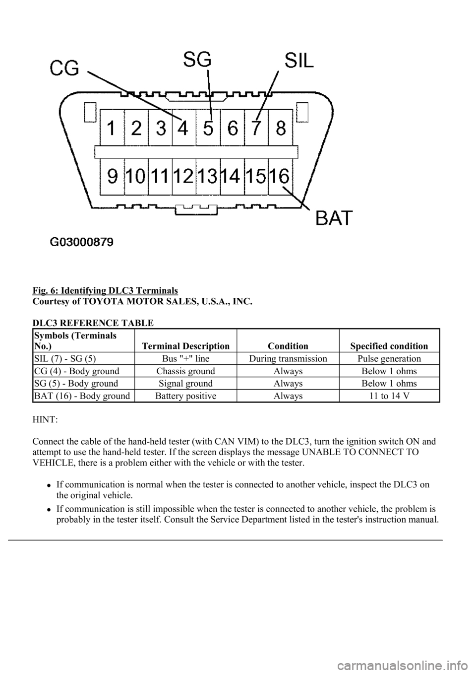
Fig. 6: Identifying DLC3 Terminals
Courtesy of TOYOTA MOTOR SALES, U.S.A., INC.
DLC3 REFERENCE TABLE
HINT:
Connect the cable of the hand-held tester (with CAN VIM) to the DLC3, turn the ignition switch ON and
attempt to use the hand-held tester. If the screen displays the message UNABLE TO CONNECT TO
VEHICLE, there is a problem either with the vehicle or with the tester.
If communication is normal when the tester is connected to another vehicle, inspect the DLC3 on
the original vehicle.
If communication is still impossible when the tester is connected to another vehicle, the problem is
probabl
y in the tester itself. Consult the Service Department listed in the tester's instruction manual.
Symbols (Terminals
No.)
Terminal DescriptionConditionSpecified condition
SIL (7) - SG (5)Bus "+" lineDuring transmissionPulse generation
CG (4) - Body groundChassis groundAlwaysBelow 1 ohms
SG (5) - Body groundSignal groundAlwaysBelow 1 ohms
BAT (16) - Body groundBattery positiveAlways11 to 14 V
Page 1997 of 4500
Fig. 7: Connecting Hand-Held Tester To DLC3
Courtesy of TOYOTA MOTOR SALES, U.S.A., INC.
3.INSPECT BATTERY VOLTAGE
Standard: 11 to 14 V
If voltage is below 11 V, recharge the battery before proceeding.
1.ACTIVE TEST
HINT:
Performing the hand-held tester's ACTIVE TEST allows relay, VSV, actuator and other items to be
operated without removing any parts. Performing the ACTIVE TEST early in troubleshooting is one way
to save time.
a. Connect the hand-held tester (with CAN VIM) to the DLC3.
b. Turn the ignition switch ON.
Page 2000 of 4500
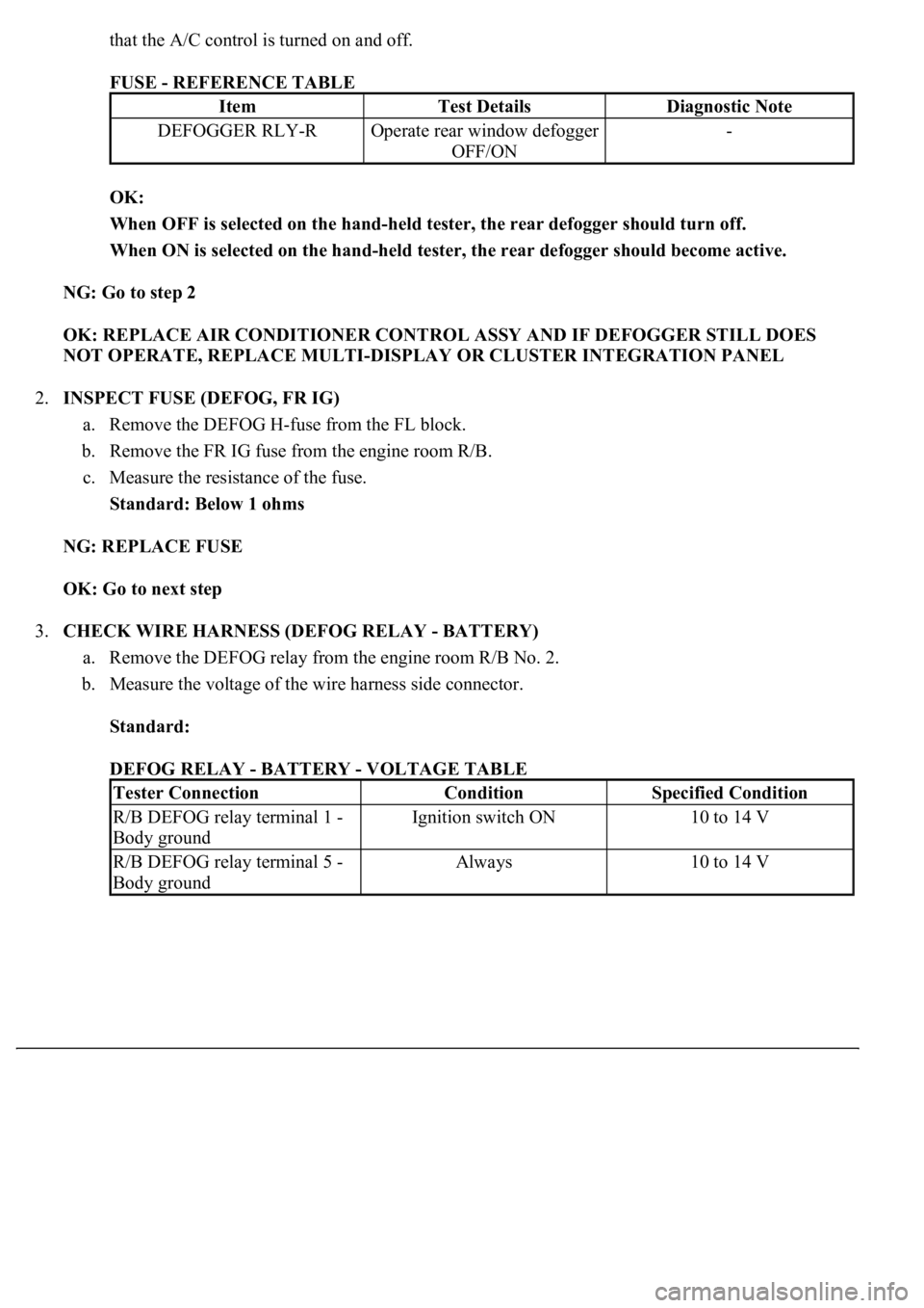
that the A/C control is turned on and off.
FUSE - REFERENCE TABLE
OK:
When OFF is selected on the hand-held tester, the rear defogger should turn off.
When ON is selected on the hand-held tester, the rear defogger should become active.
NG: Go to step 2
OK: REPLACE AIR CONDITIONER CONTROL ASSY AND IF DEFOGGER STILL DOES
NOT OPERATE, REPLACE MULTI-DISPLAY OR CLUSTER INTEGRATION PANEL
2.INSPECT FUSE (DEFOG, FR IG)
a. Remove the DEFOG H-fuse from the FL block.
b. Remove the FR IG fuse from the engine room R/B.
c. Measure the resistance of the fuse.
Standard: Below 1 ohms
NG: REPLACE FUSE
OK: Go to next step
3.CHECK WIRE HARNESS (DEFOG RELAY - BATTERY)
a. Remove the DEFOG relay from the engine room R/B No. 2.
b. Measure the voltage of the wire harness side connector.
Standard:
DEFOG RELAY - BATTERY - VOLTAGE TABLE
ItemTest DetailsDiagnostic Note
DEFOGGER RLY-ROperate rear window defogger
OFF/ON-
Tester ConnectionConditionSpecified Condition
R/B DEFOG relay terminal 1 -
Body groundIgnition switch ON10 to 14 V
R/B DEFOG relay terminal 5 -
Body groundAlways10 to 14 V
Page 2010 of 4500
1994On Right Side Of Engine Compartment & Below Glove Box
1995
3.8LOn Right Side Of Engine Compartment & Below Glove Box
4.6LBehind Right Side Of Dash, Below Glove Box
1996Lower Right Side Of Dash, Below Glove Box
Crown Victoria, Grand Marquis & Lincoln Town Car
1983 & 1987On Right Fender Apron
1985-86 & 1988-90On Left Fender Apron
1992On Left Front Fender Panel
1993-94On Top Of Left Front Wheelwell
Escort, EXP, Lynx & Tracer
1985-90On Right Fender Apron Near Firewall
1991On Left Rear Of Engine Compartment
1992On Right Rear Of Engine Compartment, Near Cowl
1993-95On Left Side Of Firewall
LTD & Marquis
1983On Left Fender Apron
1984-86On Left Rear Corner Of Engine Compartment
Mark VII
1984-87On Right Rear Corner Of Engine Compartment
1988-90Front Of Right Fender Apron
1991On Right Side Of Engine Compartment, Near Thermactor
Solenoids
Mark VIII
1993-96On Top Of Left Wheelwell
Mustang
1980-85On Center Of Left Front Fender Apron
1986-91On Left Rear Corner Of Engine Compartment
1992On Left Shock Tower, Near Ignition Coil
19932 Connectors On Right Front Strut Tower
1994-95Behind Right Front Strut Tower & Right Of Steering Column
Probe
1991-92On Left Rear Corner Of Engine Compartment
1993DLC - Behind Left Side Of Dash; STI Connector - On Left
Inner Fender Panel
1994-95On Left Front Inner Fender Panel
Sable & Taurus
1986-87 (3.0L Only)Near Alternator
1988-90
2.5LOn Engine Harness Near PCV Hose
3.0LOn Right Rear Corner Of Engine Compartment
Page 2026 of 4500
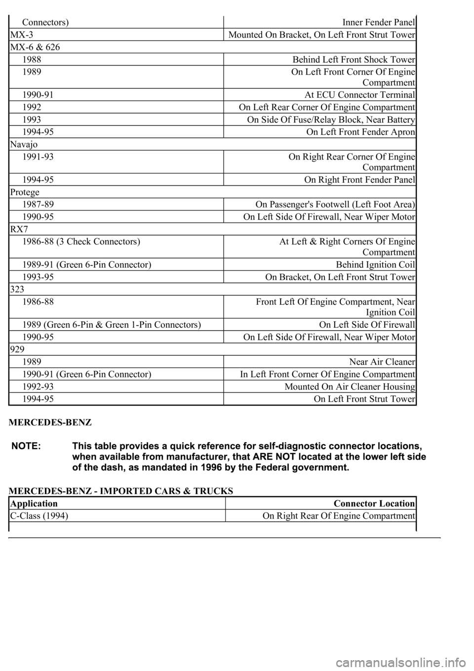
MERCEDES-BENZ
MERCEDES-BENZ - IMPORTED CARS & TRUCKS
Connectors)Inner Fender Panel
MX-3Mounted On Bracket, On Left Front Strut Tower
MX-6 & 626
1988Behind Left Front Shock Tower
1989On Left Front Corner Of Engine
Compartment
1990-91At ECU Connector Terminal
1992On Left Rear Corner Of Engine Compartment
1993On Side Of Fuse/Relay Block, Near Battery
1994-95On Left Front Fender Apron
Navajo
1991-93On Right Rear Corner Of Engine
Compartment
1994-95On Right Front Fender Panel
Protege
1987-89On Passenger's Footwell (Left Foot Area)
1990-95On Left Side Of Firewall, Near Wiper Motor
RX7
1986-88 (3 Check Connectors)At Left & Right Corners Of Engine
Compartment
1989-91 (Green 6-Pin Connector)Behind Ignition Coil
1993-95On Bracket, On Left Front Strut Tower
323
1986-88Front Left Of Engine Compartment, Near
Ignition Coil
1989 (Green 6-Pin & Green 1-Pin Connectors)On Left Side Of Firewall
1990-95On Left Side Of Firewall, Near Wiper Motor
929
1989Near Air Cleaner
1990-91 (Green 6-Pin Connector)In Left Front Corner Of Engine Compartment
1992-93Mounted On Air Cleaner Housing
1994-95On Left Front Strut Tower
ApplicationConnector Location
C-Class (1994)On Right Rear Of Engine Compartment
Page 2027 of 4500
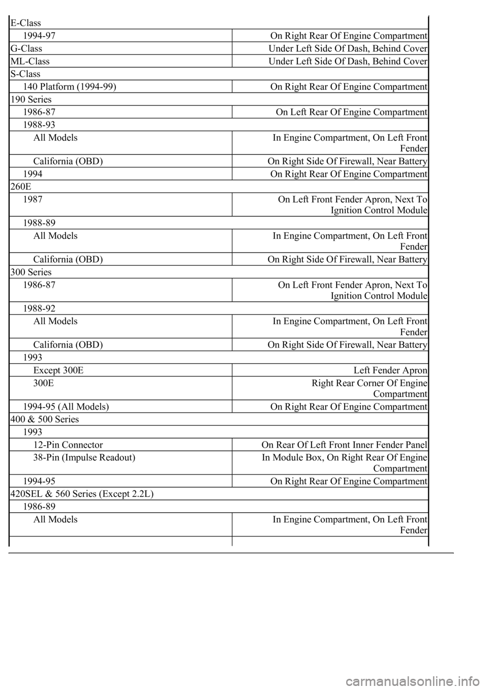
E-Class
1994-97On Right Rear Of Engine Compartment
G-ClassUnder Left Side Of Dash, Behind Cover
ML-ClassUnder Left Side Of Dash, Behind Cover
S-Class
140 Platform (1994-99)On Right Rear Of Engine Compartment
190 Series
1986-87On Left Rear Of Engine Compartment
1988-93
All ModelsIn Engine Compartment, On Left Front
Fender
California (OBD)On Right Side Of Firewall, Near Battery
1994On Right Rear Of Engine Compartment
260E
1987On Left Front Fender Apron, Next To
Ignition Control Module
1988-89
All ModelsIn Engine Compartment, On Left Front
Fender
California (OBD)On Right Side Of Firewall, Near Battery
300 Series
1986-87On Left Front Fender Apron, Next To
Ignition Control Module
1988-92
All ModelsIn Engine Compartment, On Left Front
Fender
California (OBD)On Right Side Of Firewall, Near Battery
1993
Except 300ELeft Fender Apron
300ERight Rear Corner Of Engine
Compartment
1994-95 (All Models)On Right Rear Of Engine Compartment
400 & 500 Series
1993
12-Pin ConnectorOn Rear Of Left Front Inner Fender Panel
38-Pin (Impulse Readout)In Module Box, On Right Rear Of Engine
Compartment
1994-95On Right Rear Of Engine Compartment
420SEL & 560 Series (Except 2.2L)
1986-89
All ModelsIn Engine Compartment, On Left Front
Fender
Page 2034 of 4500
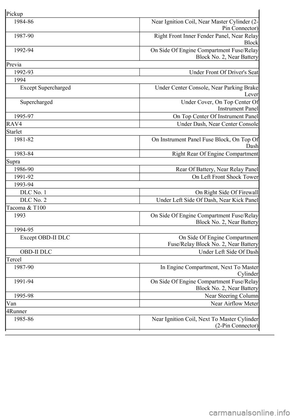
Pickup
1984-86Near Ignition Coil, Near Master Cylinder (2-
Pin Connector)
1987-90Right Front Inner Fender Panel, Near Relay
Block
1992-94On Side Of Engine Compartment Fuse/Relay
Block No. 2, Near Battery
Previa
1992-93Under Front Of Driver's Seat
1994
Except SuperchargedUnder Center Console, Near Parking Brake
Lever
SuperchargedUnder Cover, On Top Center Of
Instrument Panel
1995-97On Top Center Of Instrument Panel
RAV4Under Dash, Near Center Console
Starlet
1981-82On Instrument Panel Fuse Block, On Top Of
Dash
1983-84Right Rear Of Engine Compartment
Supra
1986-90Rear Of Battery, Near Relay Panel
1991-92On Left Front Shock Tower
1993-94
DLC No. 1On Right Side Of Firewall
DLC No. 2Under Left Side Of Dash, Near Kick Panel
Tacoma & T100
1993On Side Of Engine Compartment Fuse/Relay
Block No. 2, Near Battery
1994-95
Except OBD-II DLCOn Side Of Engine Compartment
Fuse/Relay Block No. 2, Near Battery
OBD-II DLCUnder Left Side Of Dash
Tercel
1987-90In Engine Compartment, Next To Master
Cylinder
1991-94On Side Of Engine Compartment Fuse/Relay
Block No. 2, Near Battery
1995-98Near Steering Column
VanNear Airflow Meter
4Runner
1985-86Near Ignition Coil, Next To Master Cylinder
(2-Pin Connector)