Page 1777 of 4500
b. Turn the ignition switch to OFF.
c. Connect the hand-held tester to DLC3.
d. Turn the ignition switch to ON.
e. Operate the hand-held tester according to the steps on the display and select "DATA LIST".
METER:
Fig. 36: Meter Data List Item Reference Chart
Courtesy of TOYOTA MOTOR SALES, U.S.A., INC.
BODY No.2:
Fig. 37: Body No.2 Data List Item Reference Chart
Courtesy of TOYOTA MOTOR SALES, U.S.A., INC.
BODY No.3:
Page 1780 of 4500

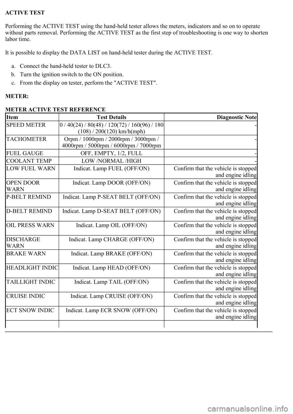
ACTIVE TEST
Performing the ACTIVE TEST using the hand-held tester allows the meters, indicators and so on to operate
without parts removal. Performing the ACTIVE TEST as the first step of troubleshooting is one way to shorten
labor time.
It is possible to display the DATA LIST on hand-held tester during the ACTIVE TEST.
a. Connect the hand-held tester to DLC3.
b. Turn the ignition switch to the ON position.
c. From the display on tester, perform the "ACTIVE TEST".
METER:
METER ACTIVE TEST REFERENCE
ItemTest DetailsDiagnostic Note
SPEED METER0 / 40(24) / 80(48) / 120(72) / 160(96) / 180
(108) / 200(120) km/h(mph)-
TACHOMETEROrpm / 1000rpm / 2000rpm / 3000rpm /
4000rpm / 5000rpm / 6000rpm / 7000rpm-
FUEL GAUGEOFF, EMPTY, 1/2, FULL-
COOLANT TEMPLOW /NORMAL /HIGH-
LOW FUEL WARNIndicat. Lamp FUEL (OFF/ON)Confirm that the vehicle is stopped
and engine idling
OPEN DOOR
WARNIndicat. Lamp DOOR (OFF/ON)Confirm that the vehicle is stopped
and engine idling
P-BELT REMINDIndicat. Lamp P-SEAT BELT (OFF/ON)Confirm that the vehicle is stopped
and engine idling
D-BELT REMINDIndicat. Lamp D-SEAT BELT (OFF/ON)Confirm that the vehicle is stopped
and engine idling
OIL PRESS WARNIndicat. Lamp OIL (OFF/ON)Confirm that the vehicle is stopped
and engine idling
DISCHARGE
WARNIndicat. Lamp CHARGE (OFF/ON)Confirm that the vehicle is stopped
and engine idling
BRAKE WARNIndicat. Lamp BRAKE (OFF/ON)Confirm that the vehicle is stopped
and engine idling
HEADLIGHT INDICIndicat. Lamp HEAD (OFF/ON)Confirm that the vehicle is stopped
and engine idling
TAILLIGHT INDICIndicat. Lamp TAIL (OFF/ON)Confirm that the vehicle is stopped
and engine idling
CRUISE INDICIndicat. Lamp CRUISE (OFF/ON)Confirm that the vehicle is stopped
and engine idling
ECT SNOW INDICIndicat. Lamp ECR SNOW (OFF/ON)Confirm that the vehicle is stopped
and engine idling
Page 1784 of 4500
b. Measure the voltage according to the value (s) in the table below.
Standard
COMBINATION METER VOLTAGE SPECIFICATIONS
NG: REPAIR OR REPLACE HARNESS OR CONNECTOR
Fig. 44: Identifying Combination Meter Connector Terminals (Wire Harness View)
Courtesy of TOYOTA MOTOR SALES, U.S.A., INC.
OK: REPLACE COMBINATION METER ASSY (SEE OVERHAUL
)
C12-11 - Body groundAlwaysBelow 1 ohms
C12-22 - Body groundAlwaysBelow 1ohms
Terminal NoConditionSpecified condition
C12-12 - Body groundAlways10 to 14 V
C12-13 - Body groundAlways10 to 14 V
C12-1 - Body groundIgnition switch ACC or ON10 to 14 V
Page 1791 of 4500
Fig. 48: Identifying C12 And S42 Connectors
Courtesy of TOYOTA MOTOR SALES, U.S.A., INC.
NG: REPAIR OR REPLACE HARNESS AND CONNECTOR
OK: GO TO NEXT STEP
6.INSPECT ABS & TRACTION ACTUATOR ASSY (VSC)
a. Disconnect the S42 connector.
b. Measure the voltage according to the value (s) in the table below.
Standard
S42 connector VOLTAGE SPECIFICATIONS
NG: REPLACE COMBINATION METER ASSY (SEE OVERHAUL
)
Fig. 49: Identifying S42 Connector Terminals
Courtesy of TOYOTA MOTOR SALES, U.S.A., INC.
OK: GO TO BRAKE CONTROL SYSTEM (SEE HOW TO PROCEED WITH
TROUBLESHOOTING )
Tester ConnectionConditionSpecified Condition
S42-12 - Body groundIgnition switch ON10 to 14 V
Page 1797 of 4500
Fig. 53: Identifying C12 And E2 Connectors
Courtesy of TOYOTA MOTOR SALES, U.S.A., INC.
NG: REPAIR OR REPLACE HARNESS AND CONNECTOR
OK: GO TO NEXT STEP
6.INSPECT COMBINATION METER ASSY
a. Disconnect the E2 connector.
b. Measure the voltage according to the value (s) in the table below.
Standard
E2 CONNECTOR VOLTAGE SPECIFICATIONS
NG: REPLACE COMBINATION METER ASSY (SEE OVERHAUL
)
Fig. 54: Identifying E2 Connector
Tester ConnectionConditionSpecified Condition
E2-16 - Body groundIgnition switch ON10 to 14 V
Page 1800 of 4500

Courtesy of TOYOTA MOTOR SALES, U.S.A., INC.
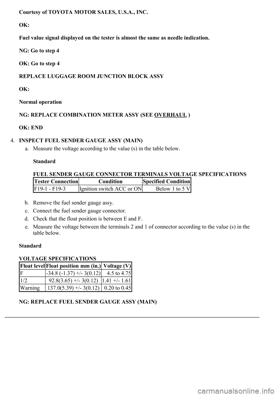
OK:
Fuel value signal displayed on the tester is almost the same as needle indication.
NG: Go to step 4
OK: Go to step 4
REPLACE LUGGAGE ROOM JUNCTION BLOCK ASSY
OK:
Normal operation
NG: REPLACE COMBINATION METER ASSY (SEE OVERHAUL
)
OK: END
4.INSPECT FUEL SENDER GAUGE ASSY (MAIN)
a. Measure the voltage according to the value (s) in the table below.
Standard
FUEL SENDER GAUGE CONNECTOR TERMINALS VOLTAGE SPECIFICATIONS
b. Remove the fuel sender gauge assy.
c. Connect the fuel sender gauge connector.
d. Check that the float position is between E and F.
e. Measure the voltage between the terminals 2 and 1 of connector according to the value (s) in the
table below.
Standard
VOLTAGE SPECIFICATIONS
NG: REPLACE FUEL SENDER GAUGE ASSY (MAIN)
Tester ConnectionConditionSpecified Condition
F19-1 - F19-3Ignition switch ACC or ONBelow 1 to 5 V
Float levelFloat position mm (in.)Voltage (V)
F-34.8 (-1.37) +/- 3(0.12)4.5 to 4.75
1/292.8(3.65) +/- 3(0.12)1.41 +/- 1.61
Warning137.0(5.39) +/- 3(0.12)0.20 to 0.45
Page 1805 of 4500
Fig. 60: Identifying Fuel Sender Gauge Assy And Luggage Room Junction Block Assy Connector
Terminals
Courtesy of TOYOTA MOTOR SALES, U.S.A., INC.
NG: REPAIR OR REPLACE HARNESS OR CONNECTOR
OK: GO TO NEXT STEP
6.INSPECT FUEL SENDER GAUGE ASSY (SUB)
a. Measure the voltage according to the value (s) in the table below.
Standard
VOLTAGE SPECIFICATIONS
b. Remove the fuel sender gauge assy.
c. Connect the fuel sender gauge connector.
d. Check that the float position is between E and F.
e. Measure the voltage between the terminals 2 and 1 of connector according to the value (s) in the
table below.
Standard
VOLTAGE SPECIFICATIONS
Tester ConnectionConditionSpecified Condition
F20-1 - F20-3Ignition switch ACC or ONBelow 1 to 5 V
Float levelFloat position mm (in.)Voltage (V)
F1.4(0.06) +/- 3(0.12)4.5 to 4.75
1/2190.2(7.49) +/- 3(0.12)0.45 +/- 0.65
Warning195.7(7.70) +/- 3(0.12)0.20 to 0.45
Page 1823 of 4500
Fig. 73: Identifying B5 And A25 Connector Terminals
Courtesy of TOYOTA MOTOR SALES, U.S.A., INC.
NG: REPAIR OR REPLACE HARNESS OR CONNECTOR
OK: REPLACE AIRBAG SENSOR ASSY CENTER (SEE HOW TO PROCEED WITH
TROUBLESHOOTING )
6.INSPECT COMBINATION METER ASSY
a. Disconnect the clock assy connector.
b. Measure the voltage according to the value (s) in the table below.
Standard
VOLTAGE SPECIFICATIONS
NG: Go to step 8
Fig. 74: Identifying C12 Connector Terminals
Terminal NoConditionSpecified condition
C12-9 - Body groundIgnition switch ON, Passenger seat belt is unfastened10 to 14 V