Page 1754 of 4500
5.SETTING COMPASS
Fig. 18: Compass Setting Flow Chart
Courtesy of TOYOTA MOTOR SALES, U.S.A., INC.
6.SELECTING DISPLAY MODE
a. Turn the ignition switch to the ON position.
b. Check that the compass display indicates an azimuthal direction (N, NE, E, SE, S, SW, W, or NW).
7.ZONE SETTING MODE
Usin
g the hand-held tester, select the customize menu.
Page 1762 of 4500
Fig. 26: Identifying Terminals Of ECU (Combination Meter Assy)
Courtesy of TOYOTA MOTOR SALES, U.S.A., INC.
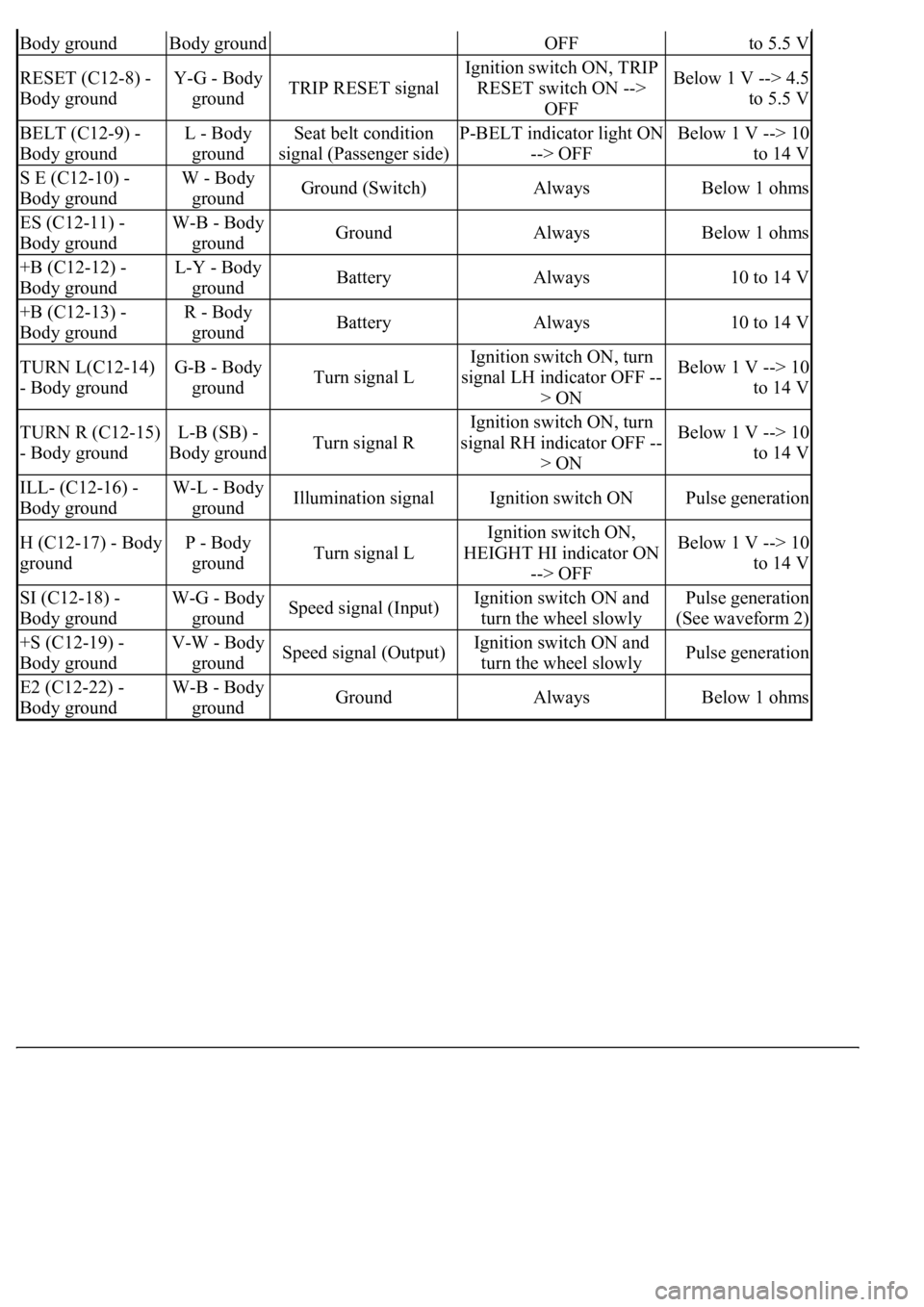
COMBINATION METER ASSY CONNECTOR TERMINALS REFERENCE
Symbols
(Terminals No.)Wiring
ColorTerminal DescriptionConditionSpecified
Condition
IG + (C12-1) -
Body groundY - Body
groundIgnition switch signal
(ON)Ignition switch OFF -->
ONBelow 1 V --> 10
to 14 V
MPX + (C12-2) -
Body groundGR-B -
Body groundMultiplex
communication signal--
MPX- (C12-3) -
Body groundGR-B -
Body groundMultiplex
communication signal--
S (C12-4) - Body
groundB-Y - Body
groundTachometer signalEngine runningPulse generation
(See waveform 1)
CHECK (C12-5) -
Body groundY-R - Body
groundCHECK ENGINE
signalCHECK ENGINE warning
light ON --> OFFBelow 1 V --> 10
to 14 V
TEMS (C12-6) -
Body groundY - Body
groundTEMS SPORT signalTEMS SPORT indicator
light ON --> OFFBelow 1 V --> 10
to 14 V
A/B (C12-7) - V-R (W) - ODO/TRIP signalIgnition switch ON,
ODO/TRIP switch ON -->
Below 1 V --> 4.5
Page 1763 of 4500

Body groundBody groundOFFto 5.5 V
RESET (C12-8) -
Body groundY-G - Body
groundTRIP RESET signal
Ignition switch ON, TRIP
RESET switch ON -->
OFFBelow 1 V --> 4.5
to 5.5 V
BELT (C12-9) -
Body groundL - Body
groundSeat belt condition
signal (Passenger side)P-BELT indicator light ON
--> OFFBelow 1 V --> 10
to 14 V
S E (C12-10) -
Body groundW - Body
groundGround (Switch)AlwaysBelow 1 ohms
ES (C12-11) -
Body groundW-B - Body
groundGroundAlwaysBelow 1 ohms
+B (C12-12) -
Body groundL-Y - Body
groundBatteryAlways10 to 14 V
+B (C12-13) -
Body groundR - Body
groundBatteryAlways10 to 14 V
TURN L(C12-14)
- Body groundG-B - Body
groundTurn signal L
Ignition switch ON, turn
signal LH indicator OFF --
> ONBelow 1 V --> 10
to 14 V
TURN R (C12-15)
- Body groundL-B (SB) -
Body groundTurn signal R
Ignition switch ON, turn
signal RH indicator OFF --
> ONBelow 1 V --> 10
to 14 V
ILL- (C12-16) -
Body groundW-L - Body
groundIllumination signalIgnition switch ONPulse generation
H (C12-17) - Body
groundP - Body
groundTurn signal L
Ignition switch ON,
HEIGHT HI indicator ON
--> OFFBelow 1 V --> 10
to 14 V
SI (C12-18) -
Body groundW-G - Body
groundSpeed signal (Input)Ignition switch ON and
turn the wheel slowlyPulse generation
(See waveform 2)
+S (C12-19) -
Body groundV-W - Body
groundSpeed signal (Output)Ignition switch ON and
turn the wheel slowlyPulse generation
E2 (C12-22) -
Body groundW-B - Body
groundGroundAlwaysBelow 1 ohms
Page 1768 of 4500
Fig. 31: Identifying DLC3 Connector Terminals
Courtesy of TOYOTA MOTOR SALES, U.S.A., INC.
DLC3 CONNECTOR TERMINALS REFERENCE
HINT:
If the display shows UNABLE TO CONNECT TO VEHICLE when you have connected the cable of the
hand-held tester to the DLC3, turned the ignition switch ON and operated the tester, there is a problem on
the vehicle side or tool side.
Symbols (Terminals No.)Terminals DescriptionConditionSpecified condition
CG(4) - Body groundChassis groundAlwaysBelow 1 ohms
BAT(16) - Body groundBattery positiveAlways11 to 14 V
CANH(6) - CANL(14)HIGH-level CAN bus lineIG switch OFF54 ohms to 67ohms
CANH(6) - Body groundHIGH-level CAN bus lineIG switch OFF1 Mohms or higher
CANH(6) - CG(4)HIGH-level CAN bus lineIG switch OFF3 Kohms or higher
CANL(14) - Body groundLOW-level CAN bus lineIG switch OFF1 Mohms or higher
CANL(14) - CG(4)LOW-level CAN bus lineIG switch OFF3 Kohms or higher
Page 1769 of 4500
If the communication is normal when the tool is connected to another vehicle, inspect the DLC3 on
the original vehicle.
If the communication is still impossible when the tool is connected to another vehicle, the problem
is probably in the tool itself, so consult the Service Department listed in the tool's instruction
manual.
2.DIAGNOSIS CHECK (MULTI- INFORMATION DISPLAY)
a. Switch to diagnosis mode
1. Connect terminal 13 (TC) and 4 (CG) of the DLC3 using SST.
Fig. 32: Identifying Terminal 13 (TC) And 4 (CG) Of DLC3
Courtesy of TOYOTA MOTOR SALES, U.S.A., INC.
2. The display in the warning area shows "DIAG" when the ignition switch is turned to the ON
position.
3. Each system can be switched by pushing the "DISP1" switch on the steering pad switch.
HINT:
Dia
gnosis checks for the EFI, VSC and CRUISE systems can be done by using the displayed items
Page 1772 of 4500
b. Read DTCs
1. "OK" is displayed if the system is normal while "NG" is displayed if it is malfunctioning.
HINT:
When the ignition switch is turned to any position but ON during diagnosis mode, the mode is
canceled.
Page 1774 of 4500
signal data.
Fig. 35: Display E And
- -
Courtesy of TOYOTA MOTOR SALES, U.S.A., INC.
WATER TEMPERATURE GAUGE:
WATER TEMPERATURE GAUGE FAIL-SAFE REFERENCE
FUEL SIGNAL (FUEL INJECTION SIGNAL):
FUEL SIGNAL (FUEL INJECTION SIGNAL) FAIL-SAFE REFERENCE
FUEL SIGNAL (GAUGE SIGNAL):
ConditionResponseRecovery
Water temperature data is interrupted for
5 seconds.The gauge needle indicates
below "C".Water temperature data is
received.
ConditionResponseRecovery
While the ignition switch is in the ON
position, the fuel injection signal is
interrupted for 60 seconds.Fuel gauge calibration is
performed using average fuel
consumption data.The ignition switch is turned
from off to on and normal
data is received.
Page 1775 of 4500

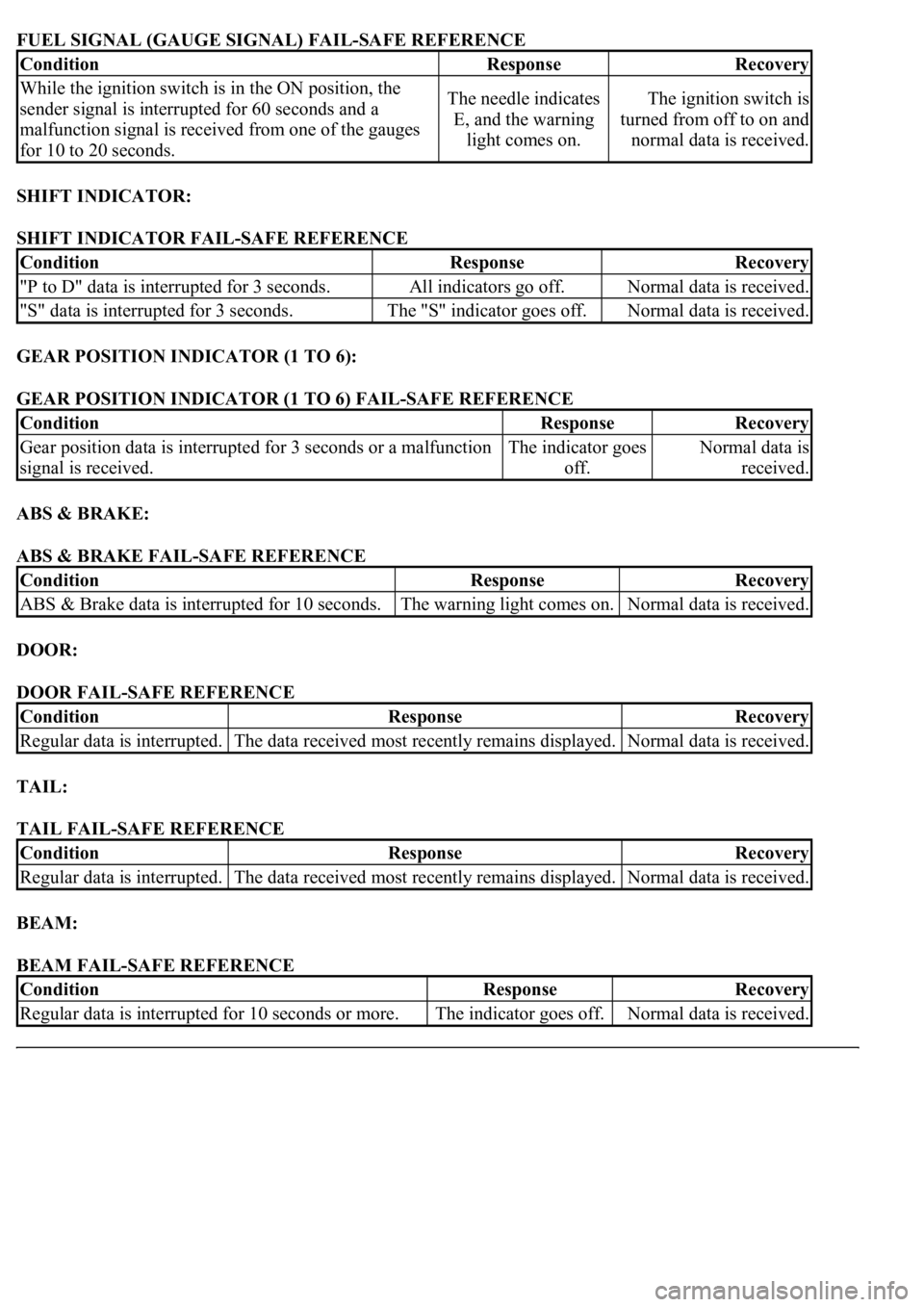
FUEL SIGNAL (GAUGE SIGNAL) FAIL-SAFE REFERENCE
SHIFT INDICATOR:
SHIFT INDICATOR FAIL-SAFE REFERENCE
GEAR POSITION INDICATOR (1 TO 6):
GEAR POSITION INDICATOR (1 TO 6) FAIL-SAFE REFERENCE
ABS & BRAKE:
ABS & BRAKE FAIL-SAFE REFERENCE
DOOR:
DOOR FAIL-SAFE REFERENCE
TAIL:
TAIL FAIL-SAFE REFERENCE
BEAM:
BEAM FAIL-SAFE REFERENCE
ConditionResponseRecovery
While the ignition switch is in the ON position, the
sender signal is interrupted for 60 seconds and a
malfunction signal is received from one of the gauges
for 10 to 20 seconds.The needle indicates
E, and the warning
light comes on.The ignition switch is
turned from off to on and
normal data is received.
ConditionResponseRecovery
"P to D" data is interrupted for 3 seconds.All indicators go off.Normal data is received.
"S" data is interrupted for 3 seconds.The "S" indicator goes off.Normal data is received.
ConditionResponseRecovery
Gear position data is interrupted for 3 seconds or a malfunction
signal is received.The indicator goes
off.Normal data is
received.
ConditionResponseRecovery
ABS & Brake data is interrupted for 10 seconds.The warning light comes on.Normal data is received.
ConditionResponseRecovery
Regular data is interrupted.The data received most recently remains displayed.Normal data is received.
ConditionResponseRecovery
Regular data is interrupted.The data received most recently remains displayed.Normal data is received.
ConditionResponseRecovery
<00350048004a0058004f00440055000300470044005700440003004c00560003004c00510057004800550055005800530057004800470003004900520055000300140013000300560048004600520051004700560003005200550003005000520055004800
11[The indicator goes off.Normal data is received.