Page 972 of 4500
Fig. 9: Tightening Bleeder Plug And Release Brake Pedal
Courtesy of TOYOTA MOTOR SALES, U.S.A., INC.
6. Repeat the above procedures for the rest of the wheels to bleed the air out of the brake line.
e. Bleed the air out of the suction line according to "Step2: Inhalation" on the hand-held tester display.
1. Connect the vinyl tube to the bleeder plug at the right front wheel or the right rear wheel and
loosen the bleeder plug.
2. Operate the ABS & TRACTION actuator assy using the hand-held tester to bleed the air.
Page 973 of 4500
Fig. 10: Connecting Vinyl Tube To Bleeder Plug And Loosen Bleeder Plug
Courtesy of TOYOTA MOTOR SALES, U.S.A., INC.
3. Check that the operation has stopped, by referring to the hand-held tester display and tighten
the bleeder plug.
4. Repeat (2) and (3) until all the air in the fluid is completely bled out.
5. Tighten the bleeder plug completely.
Torque: 11 N.m (110 kgf.cm, 8 ft.lbf)
6. For the rest of the wheels, bleed the air in the same way as stated in the above procedures.
f. Bleed the air out of the pressure reduction line according to "Step3: Decrease" on the hand-held
tester display.
Page 976 of 4500
Fig. 13: Tightening Bleeder Plug And Release Brake Pedal
Courtesy of TOYOTA MOTOR SALES, U.S.A., INC.
4. Tighten the bleeder plug, then release the brake pedal.
5. Repeat (2) to (4) until all the air in the fluid is completely bled out.
6. Tighten the bleeder plug completely.
Torque: 11 N.m (110 kgf.cm, 8 ft.lbf)
7. Repeat the above procedures for the rest of the wheels to bleed the air out of the brake line.
g. Bleed the air out of the regular bleeding again according to "Step4: Increase" on the hand-held
tester display.
1. Connect the vinyl tube to either one of the bleeder plugs.
2. Depress the brake pedal several times, then loosen the bleeder plug connected to the vinyl
tube with the pedal depressed.
Page 1200 of 4500

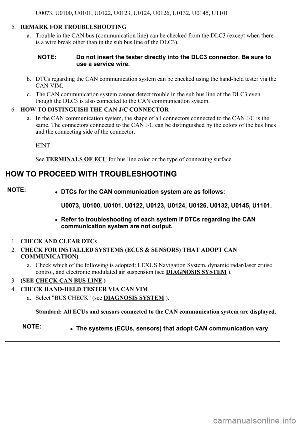
U0073, U0100, U0101, U0122, U0123, U0124, U0126, U0132, U0145, U1101
5.REMARK FOR TROUBLESHOOTING
a. Trouble in the CAN bus (communication line) can be checked from the DLC3 (except when there
is a wire break other than in the sub bus line of the DLC3).
b. DTCs regarding the CAN communication system can be checked using the hand-held tester via the
CAN VIM.
c. The CAN communication system cannot detect trouble in the sub bus line of the DLC3 even
though the DLC3 is also connected to the CAN communication system.
6.HOW TO DISTINGUISH THE CAN J/C CONNECTOR
a. In the CAN communication system, the shape of all connectors connected to the CAN J/C is the
same. The connectors connected to the CAN J/C can be distinguished by the colors of the bus lines
and the connecting side of the connector.
HINT:
See TERMINALS OF ECU
for bus line color or the type of connecting surface.
1.CHECK AND CLEAR DTCs
2.CHECK FOR INSTALLED SYSTEMS (ECUS & SENSORS) THAT ADOPT CAN
COMMUNICATION)
a. Check which of the following is adopted: LEXUS Navigation System, dynamic radar/laser cruise
control, and electronic modulated air suspension (see DIAGNOSIS SYSTEM
).
3.(SEE CHECK CAN BUS LINE
)
4.CHECK HAND-HELD TESTER VIA CAN VIM
a. Select "BUS CHECK" (see DIAGNOSIS SYSTEM
).
Standard: All ECUs and sensors connected to the CAN communication system are displayed.
Page 1201 of 4500
NO: COMMUNICATION STOP MODE TABLE (SEE PROBLEM SYMPTOMS TABLE )
YES: GO TO NEXT STEP
5.DTC COMBINATION TABLE (SEE DIAGNOSTIC TROUBLE CODE CHART
)
a. Confirm trouble according to the combination of output DTCs regarding the CAN communication
system.
HINT:
Previous CAN communication system DTCs may be the cause if CAN communication system DTCs are
output and all ECUs and sensors connected to the CAN communication system are displayed on the hand-
held tester's "BUS CHECK" screen via the CAN VIM.
6.CIRCUIT INSPECTION
7.IDENTIFICATION OF PROBLEM
8.REPAIR OR REPLACE
9.CONFIRMATION TEST
END
Page 1223 of 4500

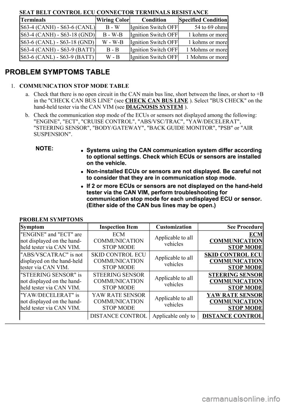
SEAT BELT CONTROL ECU CONNECTOR TERMINALS RESISTANCE
1.COMMUNICATION STOP MODE TABLE
a. Check that there is no open circuit in the CAN main bus line, short between the lines, or short to +B
in the "CHECK CAN BUS LINE" (see CHECK CAN BUS LINE
). Select "BUS CHECK" on the
hand-held tester via the CAN VIM (see DIAGNOSIS SYSTEM
).
b. Check the communication stop mode of the ECUs or sensors not displayed among the following:
"ENGINE", "ECT", "CRUISE CONTROL", "ABS/VSC/TRAC", "YAW/DECELERAT",
"STEERING SENSOR", "BODY/GATEWAY", "BACK GUIDE MONITOR", "PSB" or "AIR
SUSPENSION".
PROBLEM SYMPTOMS
TerminalsWiring ColorConditionSpecified Condition
S63-4 (CANH) - S63-6 (CANL)B - WIgnition Switch OFF54 to 69 ohms
S63-4 (CANH) - S63-18 (GND)B - W-BIgnition Switch OFF1 kohms or more
S63-6 (CANL) - S63-18 (GND)W - W-BIgnition Switch OFF1 kohms or more
S63-4 (CANH) - S63-9 (BATT)B - BIgnition Switch OFF1 Mohms or more
S63-6 (CANL) - S63-9 (BATT)W - BIgnition Switch OFF1 Mohms or more
SymptomInspection ItemCustomizationSee Procedure
"ENGINE" and "ECT" are
not displayed on the hand-
held tester via CAN VIM.ECM
COMMUNICATION
STOP MODEApplicable to all
vehiclesECM
COMMUNICATION
STOP MODE
"ABS/VSCATRAC" is not
displayed on the hand-held
tester via CAN VIM.SKID CONTROL ECU
COMMUNICATION
STOP MODEApplicable to all
vehiclesSKID CONTROL ECU
COMMUNICATION
STOP MODE
"STEERING SENSOR" is
not displayed on the hand-
held tester via CAN VIM.STEERING SENSOR
COMMUNICATION
STOP MODEApplicable to all
vehiclesSTEERING SENSOR
COMMUNICATION
STOP MODE
"YAW/DECELERAT" is
not displayed on the hand-
held tester via CAN VIM.YAW RATE SENSOR
COMMUNICATION
STOP MODEApplicable to all
vehiclesYAW RATE SENSOR
COMMUNICATION
STOP MODE
DISTANCE CONTROL Applicable only to DISTANCE CONTROL
Page 1224 of 4500

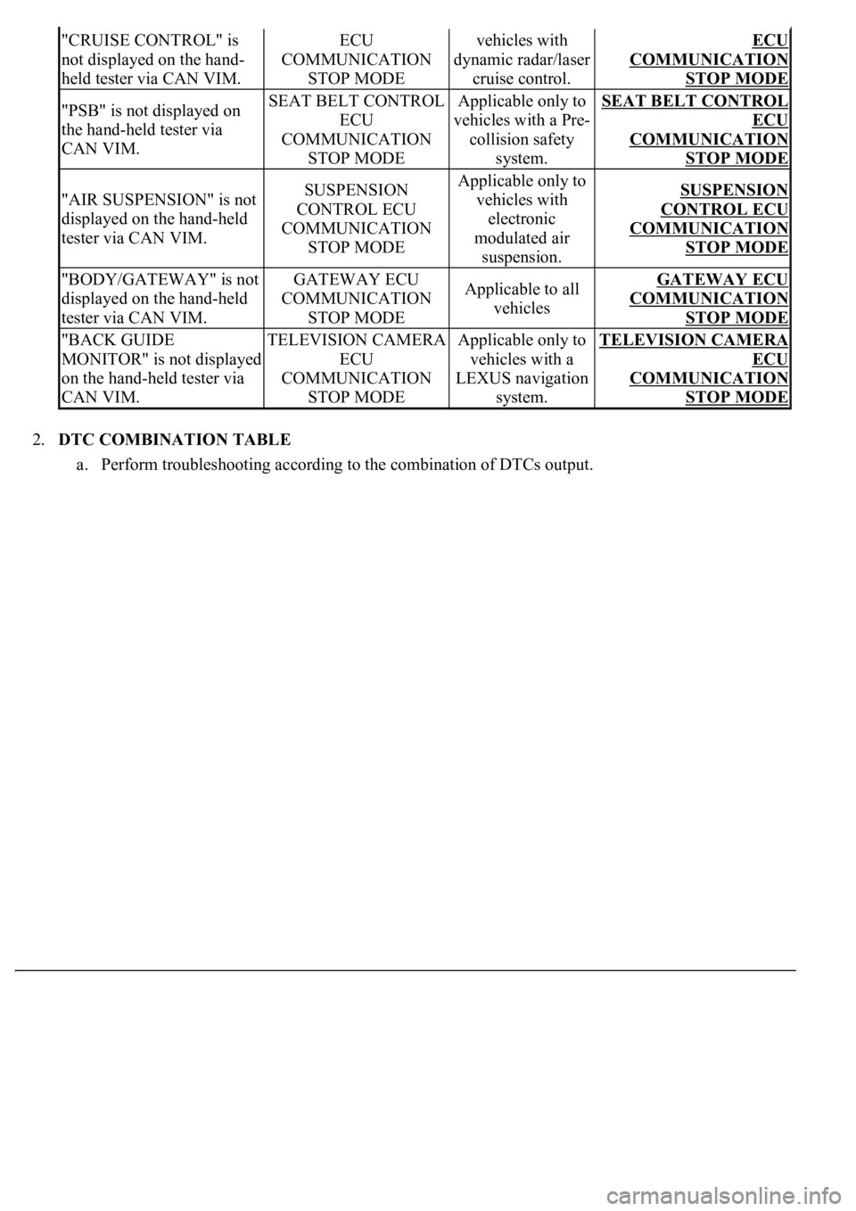
2.DTC COMBINATION TABLE
a. Perform troubleshooting according to the combination of DTCs output.
"CRUISE CONTROL" is
not displayed on the hand-
held tester via CAN VIM.ECU
COMMUNICATION
STOP MODEvehicles with
dynamic radar/laser
cruise control.ECU
COMMUNICATION
STOP MODE
"PSB" is not displayed on
the hand-held tester via
CAN VIM.SEAT BELT CONTROL
ECU
COMMUNICATION
STOP MODEApplicable only to
vehicles with a Pre-
collision safety
system.SEAT BELT CONTROL
ECU
COMMUNICATION
STOP MODE
"AIR SUSPENSION" is not
displayed on the hand-held
tester via CAN VIM.SUSPENSION
CONTROL ECU
COMMUNICATION
STOP MODEApplicable only to
vehicles with
electronic
modulated air
suspension.SUSPENSION
CONTROL ECU
COMMUNICATION
STOP MODE
"BODY/GATEWAY" is not
displayed on the hand-held
tester via CAN VIM.GATEWAY ECU
COMMUNICATION
STOP MODEApplicable to all
vehiclesGATEWAY ECU
COMMUNICATION
STOP MODE
"BACK GUIDE
MONITOR" is not displayed
on the hand-held tester via
CAN VIM.TELEVISION CAMERA
ECU
COMMUNICATION
STOP MODEApplicable only to
vehicles with a
LEXUS navigation
system.TELEVISION CAMERA
ECU
COMMUNICATION
STOP MODE
Page 1227 of 4500
Fig. 27: Display OBD/MOBD Menu Screen
Courtesy of TOYOTA MOTOR SALES, U.S.A., INC.
1.BUS CHECK
HINT:
The ECUs and sensors that are properly connected to the CAN communication system can be displayed
using the hand-held tester via CAN VIM.
a. Select "BUS CHECK" from the "OBD/MOBD MENU" screen.