Page 1228 of 4500
Fig. 28: Display ENTER Button
Courtesy of TOYOTA MOTOR SALES, U.S.A., INC.
b. Press "ENTER" on the hand-held tester via CAN VIM.
Page 1229 of 4500
Fig. 29: [Displays ECUs And Sensors]
Courtesy of TOYOTA MOTOR SALES, U.S.A., INC.
c. The screen displays the ECUs and sensors that are properly connected to the CAN communication
system.
HINT:
There is a communication stop in the system of any properly connected ECUs or sensors that are
not displayed (see CHECK CAN BUS LINE
).
2.CHECK FOR INSTALLED SYSTEMS (ECUS & SENSORS) THAT ADOPT CAN
COMMUNICATION
a. Systems (ECUs, sensors) that adopt CAN communication vary depending on the vehicle's optional
settin
gs. Check which systems (ECUs, sensors) are installed on the vehicle.
Page 1231 of 4500
Dynamic
Radar/Laser
Cruise
(Maintains
vehicle-to-
vehicle
distance)
Tx
RxTx Rx Tx Rx
Vehicl
Vehi
dista
n
control
not op
e
Back
Monitor
(Exterior
view from
rear of
vehicle is
displayed
while
reversing)
Tx Rx Back m
onl
Air
Suspension
Control
(Controls
suspension
properly
based on
vehicle
conditions)
TxTx Rx Control
Meter
Display
(Displays
operation
condition
and DTCs)
TxTx RxTx
Lamp
not co
m
or remai
Pre -
collision
Safety (Skid
control ECU
brings BA in
standby
mode and
seat belt is
fastened by
seat belt
control ECU
when
distance
control ECU
determines
that collision
Rx Tx RxPre-col
l
safety sy
does
oper
a
Page 1503 of 4500

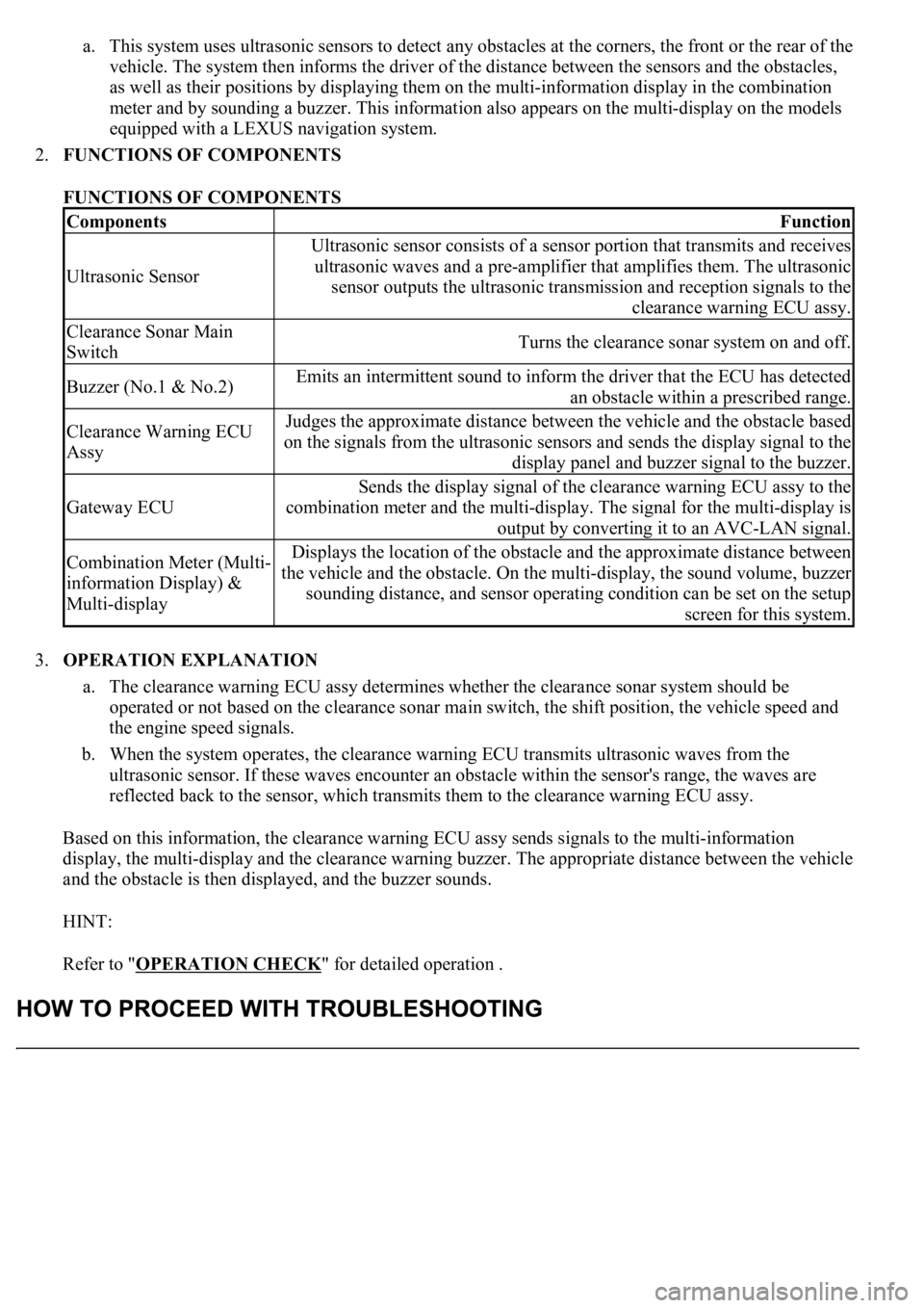
a. This system uses ultrasonic sensors to detect any obstacles at the corners, the front or the rear of the
vehicle. The system then informs the driver of the distance between the sensors and the obstacles,
as well as their positions by displaying them on the multi-information display in the combination
meter and by sounding a buzzer. This information also appears on the multi-display on the models
equipped with a LEXUS navigation system.
2.FUNCTIONS OF COMPONENTS
FUNCTIONS OF COMPONENTS
3.OPERATION EXPLANATION
a. The clearance warning ECU assy determines whether the clearance sonar system should be
operated or not based on the clearance sonar main switch, the shift position, the vehicle speed and
the engine speed signals.
b. When the system operates, the clearance warning ECU transmits ultrasonic waves from the
ultrasonic sensor. If these waves encounter an obstacle within the sensor's range, the waves are
reflected back to the sensor, which transmits them to the clearance warning ECU assy.
Based on this information, the clearance warning ECU assy sends signals to the multi-information
display, the multi-display and the clearance warning buzzer. The appropriate distance between the vehicle
and the obstacle is then displayed, and the buzzer sounds.
HINT:
Refer to "OPERATION CHECK
" for detailed operation .
ComponentsFunction
Ultrasonic Sensor
Ultrasonic sensor consists of a sensor portion that transmits and receives
ultrasonic waves and a pre-amplifier that amplifies them. The ultrasonic
sensor outputs the ultrasonic transmission and reception signals to the
clearance warning ECU assy.
Clearance Sonar Main
SwitchTurns the clearance sonar system on and off.
Buzzer (No.1 & No.2)Emits an intermittent sound to inform the driver that the ECU has detected
an obstacle within a prescribed range.
Clearance Warning ECU
AssyJudges the approximate distance between the vehicle and the obstacle based
on the signals from the ultrasonic sensors and sends the display signal to the
display panel and buzzer signal to the buzzer.
Gateway ECU
Sends the display signal of the clearance warning ECU assy to the
combination meter and the multi-display. The signal for the multi-display is
output by converting it to an AVC-LAN signal.
Combination Meter (Multi-
information Display) &
Multi-displayDisplays the location of the obstacle and the approximate distance between
the vehicle and the obstacle. On the multi-display, the sound volume, buzzer
sounding distance, and sensor operating condition can be set on the setup
screen for this system.
Page 1506 of 4500
Fig. 4: Clearance Sonar System Check Sheet
Courtesy of TOYOTA MOTOR SALES, U.S.A., INC.
1.DETECTION RANGE MEASUREMENT AND DISPLAY CHECK
Page 1508 of 4500
Fig. 5: Identifying Front And Back Sonar's Detection Ranges
Courtesy of TOYOTA MOTOR SALES, U.S.A., INC.
f. Check the multi-information display, the multi-display and the buzzer sounding condition when the
front sensor detects an obstacle.
Operation condition:
Page 1510 of 4500
Fig. 6: Identifying Front Sonar Display
Courtesy of TOYOTA MOTOR SALES, U.S.A., INC.
g. Check the multi-information display and the buzzer sounding condition when the back sensor
detects an obstacle.
Operation condition:
Back sonar:
CLEARANCE SONAR MAIN SWITCH
Page 1511 of 4500
HINT:
Clearance sonar display does not appear on the multi-display if the shift lever is moved to the
R position.
Because sound waves are used for detection range measurement, the detection range may
chan
ge slightly due to the peripheral temperature.
Ignition
switchClearance sonar main
switchShift
positionVehicle speedEngine speed
ONONR position10 km/h (6 mph) or
less2,500 RPM or
less