Page 1524 of 4500
Fig. 15: Connecting Cable Of Hand-Held Tester To Dlc3
Courtesy of TOYOTA MOTOR SALES, U.S.A., INC.
1.DATA LIST
a. Connect the hand-held tester to the DLC3.
b. Turn the ignition switch to the ON position.
c. Operate the hand-held tester according to the steps on the display and select "DATA LIST".
CSONAR:
Page 1525 of 4500
Fig. 16: Item Measurement Item/Range (Display) Normal Condition Diagnostic Note Description (1
Of 2)
Courtesy of TOYOTA MOTOR SALES, U.S.A., INC.
Page 1526 of 4500
Fig. 17: Item Measurement Item/Range (Display) Normal Condition Diagnostic Note Description (2
Of 2)
Courtesy of TOYOTA MOTOR SALES, U.S.A., INC.
2.ACTIVE TEST LIST
Page 1527 of 4500

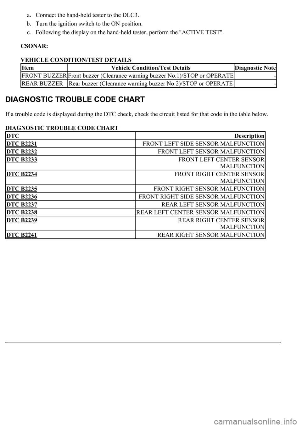
a. Connect the hand-held tester to the DLC3.
b. Turn the ignition switch to the ON position.
c. Following the display on the hand-held tester, perform the "ACTIVE TEST".
CSONAR:
VEHICLE CONDITION/TEST DETAILS
If a trouble code is displayed during the DTC check, check the circuit listed for that code in the table below.
DIAGNOSTIC TROUBLE CODE CHART
ItemVehicle Condition/Test DetailsDiagnostic Note
FRONT BUZZERFront buzzer (Clearance warning buzzer No.1)/STOP or OPERATE-
REAR BUZZERRear buzzer (Clearance warning buzzer No.2)/STOP or OPERATE-
DTCDescription
DTC B2231FRONT LEFT SIDE SENSOR MALFUNCTION
DTC B2232FRONT LEFT SENSOR MALFUNCTION
DTC B2233FRONT LEFT CENTER SENSOR
MALFUNCTION
DTC B2234FRONT RIGHT CENTER SENSOR
MALFUNCTION
DTC B2235FRONT RIGHT SENSOR MALFUNCTION
DTC B2236FRONT RIGHT SIDE SENSOR MALFUNCTION
DTC B2237REAR LEFT SENSOR MALFUNCTION
DTC B2238REAR LEFT CENTER SENSOR MALFUNCTION
DTC B2239REAR RIGHT CENTER SENSOR
MALFUNCTION
DTC B2241REAR RIGHT SENSOR MALFUNCTION
Page 1574 of 4500
Fig. 63: Clearance Sonar Main Switch Wiring Diagram
Courtesy of TOYOTA MOTOR SALES, U.S.A., INC.
INSPECTION PROCEDURE
1.READ VALUE OF HAND-HELD TESTER
a. Connect the hand-held tester to the DLC3.
b. Turn the ignition switch to the ON position.
c. Turn the hand-held tester on.
d. Turn the clearance sonar main switch on.
e. Select the item below in the DATA LIST, and read its value displayed on the hand-held tester to
check the clearance sonar main switch.
CSONAR:
Page 1575 of 4500
ITEM CONDITION DESCRIPTION
OK: PROCEED TO NEXT CIRCUIT INSPECTION SHOWN IN PROBLEM SYMPTOMS
TABLE
NG: Go To Next Step.
2.INSPECT CLEARANCE WARNING ECU ASSY (CLSW TERMINAL)
a. Disconnect the C17 connector from the clearance warning ECU assy.
b. Measure the voltage according to the value (s) in the table below.
Standard:
Fig. 64: Tester Connection Specified Condition Description Table
Courtesy of TOYOTA MOTOR SALES, U.S.A., INC.
ConditionItemStandard
Clearance Sonar Main Switch onMAIN SW"ON" is displayed
Page 1605 of 4500

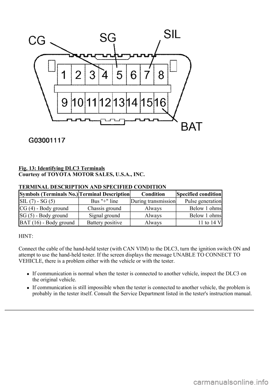
Fig. 13: Identifying DLC3 Terminals
Courtesy of TOYOTA MOTOR SALES, U.S.A., INC.
TERMINAL DESCRIPTION AND SPECIFIED CONDITION
HINT:
Connect the cable of the hand-held tester (with CAN VIM) to the DLC3, turn the ignition switch ON and
attempt to use the hand-held tester. If the screen displays the message UNABLE TO CONNECT TO
VEHICLE, there is a problem either with the vehicle or with the tester.
If communication is normal when the tester is connected to another vehicle, inspect the DLC3 on
the original vehicle.
If communication is still impossible when the tester is connected to another vehicle, the problem is
probably in the tester itself. Consult the Service Department listed in the tester's instruction manual.
Symbols (Terminals No.)Terminal DescriptionConditionSpecified condition
SIL (7) - SG (5)Bus "+" lineDuring transmissionPulse generation
CG (4) - Body groundChassis groundAlwaysBelow 1 ohms
SG (5) - Body groundSignal groundAlwaysBelow 1 ohms
BAT (16) - Body groundBattery positiveAlways11 to 14 V
Page 1743 of 4500
Fig. 10: Communication Signal Reference Chart BEAN (Column)
Courtesy of TOYOTA MOTOR SALES, U.S.A., INC.
AVC-LAN:
Fig. 11: Communication Signal Reference Chart (AVC
-LAN)
Courtesy of TOYOTA MOTOR SALES, U.S.A., INC.
1.METER GAUGE AND WARNING/INDICATOR
GAUGE:
GAUGE DETAIL
WARNING/INDICATOR:
ItemDetail
SpeedometerBased on a signal received from the wheel speed sensor, the skid control ECU
calculates vehicle speed and transmits the data to the meter (Direct line).
TachometerECM transmits engine speed to the meter display (Direct line).
Water Temperature
GaugeDisplays water temperature receiving a signal from the ECM (BEAN).
Fuel GaugeReceives the fuel sender gauge signal from the luggage room J/B ECU (BEAN).