Page 723 of 4500
elements come on during the SW check mode.
It takes about 40 seconds to complete the check.
Turn all the elements in the LCD on.
When pressing the switch, confirm beep sound is emitted.
Press the "SEEK TRACK UP" switch to enter the "System Check Screen".
Fig. 19: Identifying Disc Switch
Courtesy of TOYOTA MOTOR SALES, U.S.A., INC.
2.System Check Screen.
a. Reference:
In the system check mode, the system check and the diagnostic memory check are performed, and the
check results are displayed in ascending order of the component codes (physical address.)
TERMS MEANING CHART
TermsMeaning
Component code
(Physical address)Three-digit code (In hexadecimal) given to each device comprising AVC-LAN.
Corresponding to its function, individual symbol is provided.
Logical addressTwo-digit code (In hexadecimal) given to each function and device unit in each
Page 724 of 4500
3.Finishing Diagnostic Mode.
a. Press the "DISC" for 2 seconds or more, or turn the ignition switch off.
HINT:
Illustrations may differ from the actual vehicle depending on the device settings and options. Therefore, some
detailed areas may not be shown exactly the same as on the actual vehicle.
1.Start the diagnostic mode (SEE DIAGNOSTIC START
-UP/FINISH ).
2.Read the system check result.
1. Press the "SEEK TRACK" switch to see the check result of each component.
2. The component device code (physical address) is displayed first, and then the check result follows.
HINT:
If all check results are "good" the system judges that no DTC exists.
device comprising AVC-LAN
Page 725 of 4500
Fig. 20: Identifying Read System Check Result
Courtesy of TOYOTA MOTOR SALES, U.S.A., INC.
3.Detailed information mode (when displaying the DTC for a trouble component)
Page 726 of 4500
a. With "CHEC" or "ECHN" being displayed, press the preset switch "2" to go to the detailed
information mode.
b. Press the "SEEK TRACK" switch to display the "System check result (SYS)" and "Diagnostic
memory response (CODE)".
Fig. 21: Identifying Seek Track Switch To Display
Courtesy of TOYOTA MOTOR SALES, U.S.A., INC.
Page 728 of 4500

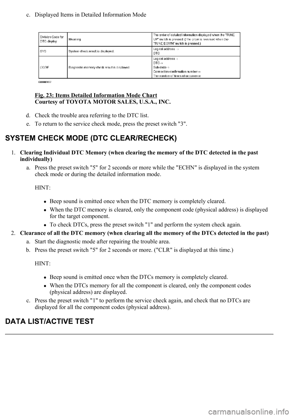
c. Displayed Items in Detailed Information Mode
Fig. 23: Items Detailed Information Mode Chart
Courtesy of TOYOTA MOTOR SALES, U.S.A., INC.
d. Check the trouble area referring to the DTC list.
e. To return to the service check mode, press the preset switch "3".
1.Clearing Individual DTC Memory (when clearing the memory of the DTC detected in the past
individually)
a. Press the preset switch "5" for 2 seconds or more while the "ECHN" is displayed in the system
check mode or during the detailed information mode.
HINT:
Beep sound is emitted once when the DTC memory is completely cleared.
When the DTC memory is cleared, only the component code (physical address) is displayed
for the target component.
To check DTCs, press the preset switch "1" and perform the system check again.
2.<0026004f004800440055004400510046004800030052004900030044004f004f00030057004b00480003002700370026000300500048005000520055005c0003000b005a004b0048005100030046004f004800440055004c0051004a00030044004f004f00
030057004b0048000300500048005000520055005c00030052[f the DTCs detected in the past)
a. Start the diagnostic mode after repairing the trouble area.
b. Press the preset switch "5" for 2 seconds or more. ("CLR" is displayed at this time.)
HINT:
Beep sound is emitted once when the DTCs memory is completely cleared.
When the DTCs memory for all the component is cleared, only the component codes
(physical address) are displayed.
c. Press the preset switch "1" to perform the service check again, and check that no DTCs are
displayed for all the component codes (physical address).
Page 729 of 4500

1.DATA LIST
HINT:
By the DATA LIST displayed on the hand-held tester, you can read the value of the switch, sensor,
actuator and so on without removing any parts. Reading the DATA LIST as the first step in
troubleshooting is one of the methods to shorten labor time.
a. Connect the hand-held tester to the DLC3.
b. Turn the ignition switch to the ON position.
c. According to the display on the tester, read the "DATA LIST".
SPAD:
Fig. 24: Spad Item Chart
Courtesy of TOYOTA MOTOR SALES, U.S.A., INC.
DIAGNOSTIC TROUBLE CODE CHART
HINT:
Titles for each unit are stated in the followin
g order: parts name (physical address) [Name indicated by DTC]
TermsDescription
Physical address3-digit, hexadecimal code assigned to all components connected to the AVC-LAN.
Individual symbols are specified based on function. Units whose names are unknown or
relevant units are displayed with physical addresses.
Logical address2-digit, hexadecimal code assigned to all the functions in the AVC-LAN system.
Page 800 of 4500
Fig. 82: Identifying Stereo Receiver Assy Connector
Courtesy of TOYOTA MOTOR SALES, U.S.A., INC.
NG: REPAIR OR REPLACE HARNESS OR CONNECTOR
OK: REPLACE RADIO RECEIVER ASSY (SEE REPLACEMENT
)
INSPECTION PROCEDURE
1.READ VALUE OF HAND-HELD TESTER
a. Connect the hand-held tester to DLC3.
b. Turn the ignition switch ON and push the hand-held tester main switch ON.
c. Select the items below in the DATA LIST, and read the displays on the hand-held tester.
SPAD:
Page 970 of 4500
Fig. 7: Connecting Hand-Held Tester To DLC3
Courtesy of TOYOTA MOTOR SALES, U.S.A., INC.
b. Connect the hand-held tester to the DLC3, then turn the ignition switch to the ON position.
c. Turn the hand-held tester power on and select "AIR BLEEDING" on the screen.
d. Perform air bleeding according to "Step 1: Increase" on the hand-held tester display.