Page 1512 of 4500
Fig. 7: Identifying Back Sonar Display
Courtesy of TOYOTA MOTOR SALES, U.S.A., INC.
h. Check the multi-information display, the multi-display and the buzzer sounding condition when the
clearance sonar sensor detects an obstacle.
Operation condition:
Front clearance sonar:
CLEARANCE SONAR MAIN SWITCH
Page 1513 of 4500
Rear clearance sonar:
CLEARANCE SONAR MAIN SWITCH
HINT:
Clearance sonar display does not appear on the multi-display if the shift lever is moved to the
R position.
Because sound waves are used for detection range measurement, the detection range may
chan
ge slightly due to the peripheral temperature.
Ignition
switchClearance sonar
main switchShift positionVehicle speedEngine speed
ONONIn any position
except P and R10 km/h (6
mph) or lessN position 1,500 RPM or less
Except N position 2,500 RPM or
less
Ignition
switchClearance sonar main
switchShift
positionVehicle speedEngine speed
ONONR position10 km/h (6 mph) or
less2,500 RPM or
less
Page 1514 of 4500
Fig. 8: Identifying Clearance Sonar Display
Courtesy of TOYOTA MOTOR SALES, U.S.A., INC.
2.INITIAL CHECK FUNCTION CHECK
a. Turn the ignition switch to the ON position.
b. Drive the engine at 2,500 RPM or less with the shift lever in any position except N, or at 1,500
RPM or less with the shift lever in the N position.
Page 1515 of 4500
c. After turning the ignition switch to the ON position, wait for 2 seconds or more, then turn the
clearance sonar main switch on. Check the multi-information display and the buzzer sounding
condition.
Standard:
After the main switch is turned on, the multi-information display shows the Fig. 9
below
for approximatel
y 2 seconds and the buzzer sounds for approximately 1 second then the
detection mode begins.
Fig. 9: Identifying Multi
-Information Display
Courtesy of TOYOTA MOTOR SALES, U.S.A., INC.
HINT:
Multi-information display:
The malfunctioning sensor blinks on the display when the wire harness or the connector is
faulty and requires repair or replacement, or when trouble is detected in the ultrasonic sensor
circuits. After the sensor operation returns to normal, the detection mode will finish
normall
y.
Page 1516 of 4500
Fig. 10: Identifying Trouble Detection Display
Courtesy of TOYOTA MOTOR SALES, U.S.A., INC.
Multi-display:
The malfunctioning sensor is displayed when the wire harness or the connector is faulty and
requires repair or replacement, or when trouble is detected in the ultrasonic sensor circuits.
After the sensor operation returns to normal, the detection mode will finish normally.
Fig. 11: Identifying Trouble Detection Display (Multi
-Display)
Page 1517 of 4500

Courtesy of TOYOTA MOTOR SALES, U.S.A., INC.
HINT:
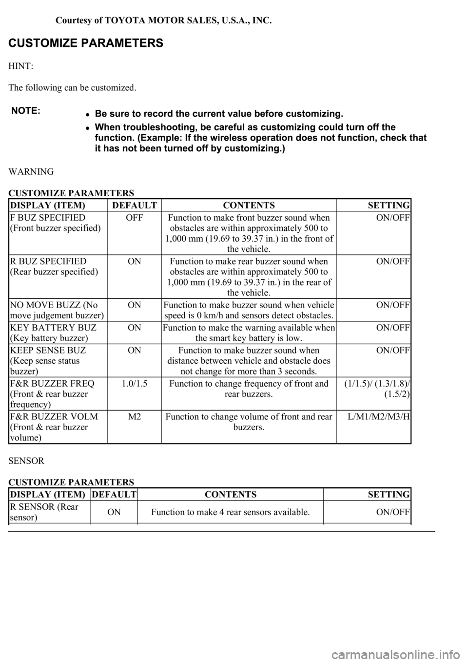
The following can be customized.
WARNING
CUSTOMIZE PARAMETERS
SENSOR
CUSTOMIZE PARAMETERS
DISPLAY (ITEM)DEFAULTCONTENTSSETTING
F BUZ SPECIFIED
(Front buzzer specified)OFFFunction to make front buzzer sound when
obstacles are within approximately 500 to
1,000 mm (19.69 to 39.37 in.) in the front of
the vehicle.ON/OFF
R BUZ SPECIFIED
(Rear buzzer specified)ONFunction to make rear buzzer sound when
obstacles are within approximately 500 to
1,000 mm (19.69 to 39.37 in.) in the rear of
the vehicle.ON/OFF
NO MOVE BUZZ (No
move judgement buzzer)ONFunction to make buzzer sound when vehicle
speed is 0 km/h and sensors detect obstacles.ON/OFF
KEY BATTERY BUZ
(Key battery buzzer)ONFunction to make the warning available when
the smart key battery is low.ON/OFF
KEEP SENSE BUZ
(Keep sense status
buzzer)ONFunction to make buzzer sound when
distance between vehicle and obstacle does
not change for more than 3 seconds.ON/OFF
F&R BUZZER FREQ
(Front & rear buzzer
frequency)1.0/1.5Function to change frequency of front and
rear buzzers.(1/1.5)/ (1.3/1.8)/
(1.5/2)
F&R BUZZER VOLM
(Front & rear buzzer
volume)M2Function to change volume of front and rear
buzzers.L/M1/M2/M3/H
DISPLAY (ITEM)DEFAULTCONTENTSSETTING
R SENSOR (Rear
sensor)ONFunction to make 4 rear sensors available.ON/OFF
Page 1518 of 4500

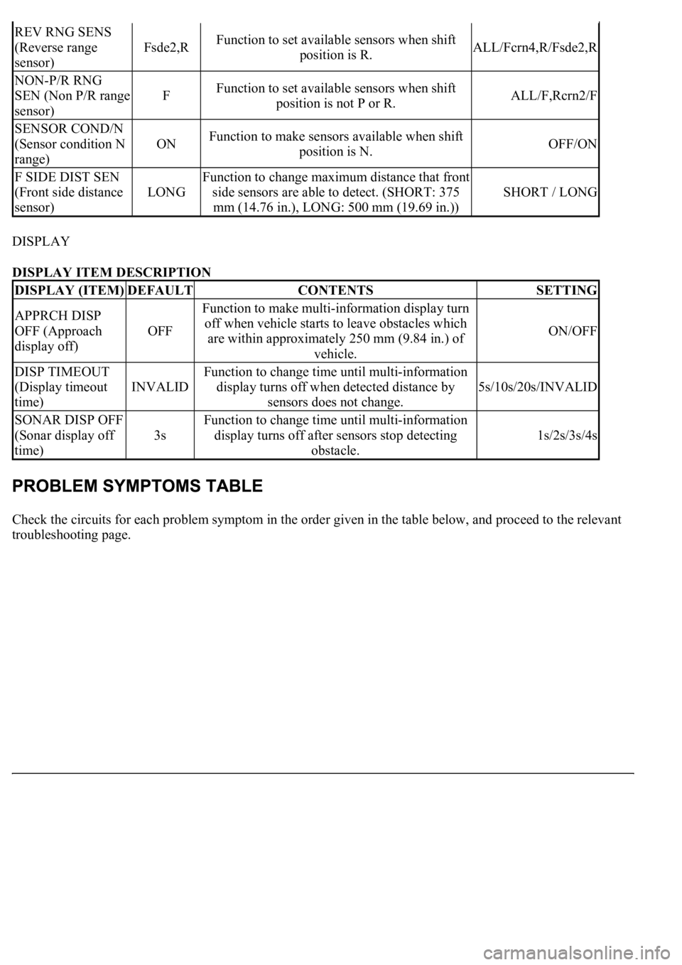
DISPLAY
DISPLAY ITEM DESCRIPTION
Check the circuits for each problem symptom in the order given in the table below, and proceed to the relevant
troubleshooting page.
REV RNG SENS
(Reverse range
sensor)
Fsde2,RFunction to set available sensors when shift
position is R.ALL/Fcrn4,R/Fsde2,R
NON-P/R RNG
SEN (Non P/R range
sensor)
FFunction to set available sensors when shift
position is not P or R.ALL/F,Rcrn2/F
SENSOR COND/N
(Sensor condition N
range)
ONFunction to make sensors available when shift
position is N.OFF/ON
F SIDE DIST SEN
(Front side distance
sensor)
LONG
Function to change maximum distance that front
side sensors are able to detect. (SHORT: 375
mm (14.76 in.), LONG: 500 mm (19.69 in.))
SHORT / LONG
DISPLAY (ITEM)DEFAULTCONTENTSSETTING
APPRCH DISP
OFF (Approach
display off)
OFF
Function to make multi-information display turn
off when vehicle starts to leave obstacles which
are within approximately 250 mm (9.84 in.) of
vehicle.
ON/OFF
DISP TIMEOUT
(Display timeout
time)
INVALID
Function to change time until multi-information
display turns off when detected distance by
sensors does not change.
5s/10s/20s/INVALID
SONAR DISP OFF
(Sonar display off
time)
3s
Function to change time until multi-information
display turns off after sensors stop detecting
obstacle.
1s/2s/3s/4s
Page 1523 of 4500

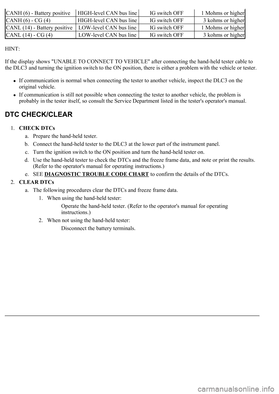
HINT:
If the display shows "UNABLE TO CONNECT TO VEHICLE" after connecting the hand-held tester cable to
the DLC3 and turning the ignition switch to the ON position, there is either a problem with the vehicle or tester.
If communication is normal when connecting the tester to another vehicle, inspect the DLC3 on the
original vehicle.
If communication is still not possible when connecting the tester to another vehicle, the problem is
probably in the tester itself, so consult the Service Department listed in the tester's operator's manual.
1.CHECK DTCs
a. Prepare the hand-held tester.
b. Connect the hand-held tester to the DLC3 at the lower part of the instrument panel.
c. Turn the ignition switch to the ON position and turn the hand-held tester on.
d. Use the hand-held tester to check the DTCs and the freeze frame data, and note or print the results.
(Refer to the operator's manual for operating instructions.)
e. SEE DIAGNOSTIC TROUBLE CODE CHART
to confirm the details of the DTCs.
2.CLEAR DTCs
a. The following procedures clear the DTCs and freeze frame data.
1. When using the hand-held tester:
Operate the hand-held tester. (Refer to the operator's manual for operating
instructions.)
2. When not using the hand-held tester:
Disconnect the battery terminals.
CANH (6) - Battery positiveHIGH-level CAN bus lineIG switch OFF1 Mohms or higher
CANH (6) - CG (4)HIGH-level CAN bus lineIG switch OFF3 kohms or higher
CANL (14) - Battery positiveLOW-level CAN bus lineIG switch OFF1 Mohms or higher
CANL (14) - CG (4)LOW-level CAN bus lineIG switch OFF3 kohms or higher