Page 4446 of 4500
assy.
2. Vehicle speed sensor
Used to calculate the vehicle running distance.
c. GPS navigation (Satellite navigation)
This method detects the absolute vehicle position using radio wave from a GPS satellite.
* GPS satellites were launched by the U.S. Department of Defence for military purposes.
Fig. 6: Identifying Autonomous Navigation
Courtesy of TOYOTA MOTOR SALES, U.S.A., INC.
NUMBER OF SATELLITES CHART
d. Map matchin
g
Number of
satellitesMeasurementDescription
2 or lessMeasurement
impossibleVehicle position cannot be obtained because the number of
satellites is not enough.
32-dimensional
measurement is possibleVehicle position is obtained based on the current longitude
and latitude. (This is less precise than 3-dimensional
measurement)
43-dimensional
measurement is possibleVehicle position is obtained based on the current
longitude, latitude and altitude.
Page 4447 of 4500

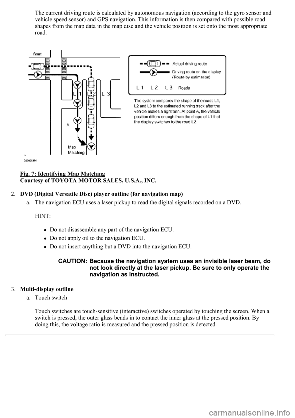
The current driving route is calculated by autonomous navigation (according to the gyro sensor and
vehicle speed sensor) and GPS navigation. This information is then compared with possible road
shapes from the map data in the map disc and the vehicle position is set onto the most appropriate
road.
Fig. 7: Identifying Map Matching
Courtesy of TOYOTA MOTOR SALES, U.S.A., INC.
2.DVD (Digital Versatile Disc) player outline (for navigation map)
a. The navigation ECU uses a laser pickup to read the digital signals recorded on a DVD.
HINT:
Do not disassemble any part of the navigation ECU.
Do not apply oil to the navigation ECU.
Do not insert anything but a DVD into the navigation ECU.
3.Multi-display outline
a. Touch switch
Touch switches are touch-sensitive (interactive) switches operated by touching the screen. When a
switch is pressed, the outer glass bends in to contact the inner glass at the pressed position. By
doing this, the voltage ratio is measured and the pressed position is detected.
Page 4448 of 4500
Fig. 8: Identifying Multi-Display Outline
Courtesy of TOYOTA MOTOR SALES, U.S.A., INC.
4.AVC-LAN Description
a. What is AVC-LAN?
AVC-LAN, an abbreviation for "Audio Visual Communication Local Area Network", is a united
standard developed by the manufacturers in affiliation with Toyota Motor Corporation. This
standard pertains to audio and visual signals as well as switch and communication signals.
Fig. 9: Identifying Avc
-Lan System
Courtesy of TOYOTA MOTOR SALES, U.S.A., INC.
b. Purpose:
Recently, car audio systems have rapidly developed and the functions vastly changed. The
conventional car audio system is being integrated with multi-media interfaces similar to those in
navigation systems. At the same time, customers are demanding higher quality from their audio
s
ystems. This is merely an overview of the standardization background. The specific purposes are
Page 4450 of 4500
Fig. 10: Identifying Bluetooth Capable Cellular
Courtesy of TOYOTA MOTOR SALES, U.S.A., INC.
1.Vehicle brought into a workshop
2.Diagnostic questioning and symptom confirmation (see CUSTOMER PROBLEM ANALYSIS
CHECK )
Ask the customer about symptoms and confirm malfunctions. Fill out the Customer Problem Analysis
check sheet.
The screen displays nothing (go to step 6, proceed to "BLACK SCREEN (NO IMAGE APPEARS
ON NAVIGATION/AUDIO SCREEN)")
Other symptoms (go to step 3)
3.Confirm the system normal condition (see SYSTEM NORMAL CONDITION CHECK
)
Applicable (This is not a malfunction.)
Not applicable (go to step 4)
4.Check the diagnostic trouble codes (see DIAGNOSTIC TROUBLE CODE CHART
)
HINT:
If the system cannot enter the diagnosis mode, inspect each AVC-LAN communication signal and
Page 4455 of 4500
Fig. 14: Identifying Color Bar Screen
Courtesy of TOYOTA MOTOR SALES, U.S.A., INC.
Page 4461 of 4500
Fig. 20: Displaying Panel Switch
Courtesy of TOYOTA MOTOR SALES, U.S.A., INC.
4.Operate each switch and check that the switch name and condition is correctly displayed.
Fig. 21: Identifying Panel Switch Check Mode
Courtesy of TOYOTA MOTOR SALES, U.S.A., INC.
HINT:
This mode checks the vehicle signal status input to the multi-display.
Illustrations may differ from the actual vehicle depending on the device settings and options. Therefore,
some detailed areas ma
y not be shown exactly the same as on the actual vehicle.
Page 4464 of 4500
Fig. 24: Identifying Vehicle Signal Chart
Courtesy of TOYOTA MOTOR SALES, U.S.A., INC.
4.When the "Vehicle Signal Check Mode" screen is displayed, check all the vehicle signal conditions.
HINT:
Only conditions having inputs are displayed.
This screen is updated once per second when input signals to the vehicle are changed.
HINT:
This mode displays GPS satellite information.
Illustrations may differ from the actual vehicle depending on the device settings and options. Therefore,
some detailed areas may not be shown exactly the same as on the actual vehicle.
1.Enter diagnostic mode (see DIAGNOSTIC START
-UP/FINISH ).
Page 4467 of 4500
Fig. 27: Identifying GPS Information Chart
Courtesy of TOYOTA MOTOR SALES, U.S.A., INC.
4.When GPS information is displayed, check the GPS conditions.
HINT:
This screen is updated once per second when input signals to the vehicle are changed.
HINT:
This mode checks the vehicle signal status to the navigation ECU.
Illustrations may differ from the actual vehicle depending on the device settings and options. Therefore,
some detailed areas may not be shown exactly the same as on the actual vehicle.
1.Enter diagnostic mode (see DIAGNOSTIC START
-UP/FINISH ).