Page 4349 of 4500
Fig. 3: Identifying Instrument Panel/Meter Components (3 Of 4)
Courtesy of TOYOTA MOTOR SALES, U.S.A., INC.
Page 4350 of 4500
Fig. 4: Identifying Instrument Panel/Meter Components (4 Of 4)
Courtesy of TOYOTA MOTOR SALES, U.S.A., INC.
Page 4400 of 4500
LOCATION
Fig. 1: Identifying Intake Air Control System Components And Replacements Location
Courtesy of TOYOTA MOTOR SALES, U.S.A., INC.
SYSTEM DIAGRAM
Page 4401 of 4500
Fig. 2: Identifying Intake Air Control System Diagram
Courtesy of TOYOTA MOTOR SALES, U.S.A., INC.
ON-VEHICLE INSPECTION
1.INSPECT INTAKE AIR CONTROL FUNCTION
Page 4421 of 4500
Fig. 7: >Identifying Terminals Of T9 ECU
Courtesy of TOYOTA MOTOR SALES, U.S.A., INC.
a. Disconnect the T9 ECU connector.
b. Measure the voltage and resistance of the wire harness side connector.
Standard:
SPECIFIED CONDITION
Symbols (Terminal
No.)
Wiring Color
Terminal
Description
Condition
Specified
Condition
CPUB (T9-1) - GND
(T9-14)V-Y - W-B+B (CPUB) power
supplyAlways10 to 14V
GND (T9-14) - Body
groundW-B - Body
groundGroundAlwaysBelow 1 ohms
Page 4423 of 4500
Fig. 8: Identifying Terminals Of Steering Lock ECU
Courtesy of TOYOTA MOTOR SALES, U.S.A., INC.
a. Disconnect the S46 ECU connector.
b. Measure the voltage and resistance of the wire harness side connector.
Standard:
SPECIFIED CONDITION
Symbols
(Terminal No.)Wiring
ColorTerminal
DescriptionConditionSpecified Condition
CPUB (S46-1) -
Body groundV-Y - Body
ground+B (CPUB)
Power supplyAlways10 to 14V
+B (S46-10)-
Body groundR-L - Body
ground+B Power supplyAlways10 to 14V
LG-B -1: No key in starter
Page 4424 of 4500

If the result is not as specified, there may be a malfunction on the wire harness side.
c. Reconnect the S46 ECU connector.
d. Measure the voltage of the connector.
Standard:
SPECIFIED CONDITION
If the result is not as specified, the ECU may have a malfunction.
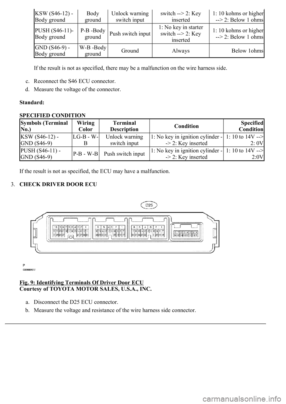
3.CHECK DRIVER DOOR ECU
Fig. 9: Identifying Terminals Of Driver Door ECU
Courtesy of TOYOTA MOTOR SALES, U.S.A., INC.
a. Disconnect the D25 ECU connector.
b. Measure the voltage and resistance of the wire harness side connector.
KSW (S46-12) -
Body groundBody
groundUnlock warning
switch inputswitch --> 2: Key
inserted1: 10 kohms or higher
--> 2: Below 1 ohms
PUSH (S46-11)-
Body groundP-B -Body
groundPush switch input
1: No key in starter
switch --> 2: Key
inserted1: 10 kohms or higher
--> 2: Below 1 ohms
GND (S46-9) -
Body groundW-B -Body
groundGroundAlwaysBelow 1ohms
Symbols (Terminal
No.)Wiring
ColorTerminal
DescriptionConditionSpecified
Condition
KSW (S46-12) -
GND (S46-9)LG-B - W-
BUnlock warning
switch input1: No key in ignition cylinder -
-> 2: Key inserted1: 10 to 14V -->
2: 0V
PUSH (S46-11) -
GND (S46-9)P-B - W-BPush switch input1: No key in ignition cylinder -
-> 2: Key inserted1: 10 to 14V -->
2:0V
Page 4426 of 4500
Fig. 10: Identifying Terminals Of DLC3
Courtesy of TOYOTA MOTOR SALES, U.S.A., INC.
SPECIFIED CONDITION
3.INSPECT BATTERY VOLTAGE Standard: 11 to 14 V
If voltage is below 11 V, recharge the battery before proceeding.
1.DATA LIST
HINT:
Symbols (Terminals No.)Terminal DescriptionConditionSpecified condition
SIL (7) - SG (5)Bus "+" lineDuring transmissionPulse generation
CG (4) - Body groundChassis groundAlwaysBelow 1 ohms
SG (5) - Body groundSignal groundAlwaysBelow 1 ohms
BAT (16) - Body groundBattery positiveAlways11 to 14V