Page 4430 of 4500
Standard: Below 1 ohms
NG: REPLACE FUSE
OK: GO TO NEXT STEP
2.INSPECT RELAY (Marking: D-IG1)
a. Remove the D-IG1 relay from the driver side J/B.
b. Measure the resistance.
Standard:
Fig. 15: Identifying terminals Of D
-IG1 Relay
Courtesy of TOYOTA MOTOR SALES, U.S.A., INC.
SPECIFIED CONDITION
NG: REPLACE RELAY
OK: GO TO NEXT STEP
Tester connectionSpecified condition
3 - 510 kohms or higher
3 - 5Below 1 ohms (when battery voltage is applied to terminals 1 and 2)
Page 4431 of 4500
3.CHECK WIRE HARNESS (DRIVER DOOR ECU - BATTERY AND BODY GROUND)
a. Disconnect the D25 ECU connector.
b. Measure the voltage and resistance of the wire harness side connector.
Standard:
Fig. 16: Identifying Terminals Of Driver Door ECU
Courtesy of TOYOTA MOTOR SALES, U.S.A., INC.
SPECIFIED CONDITION
NG: REPAIR OR REPLACE HARNESS AND CONNECTOR
OK: PROCEED TO NEXT CIRCUIT INSPECTION SHOWN ON PROBLEM SYMPTOMS
TABLE
Tester connectionConditionSpecified condition
D25-1 (GND) - Body groundAlwaysBelow 1 ohms
D25-4 (CPUB) - Body groundAlways10 to 14V
D25-6 (BDR)- Body groundAlways10 to 14V
D25-5 (SIG) Body groundIgnition switch ON10 to 14V
Page 4434 of 4500
Fig. 19: Identifying Terminals Of Front Door Courtesy Lamp Switch Assy
Courtesy of TOYOTA MOTOR SALES, U.S.A., INC.
NG: REPLACE FRONT DOOR COURTESY LAMP SWITCH ASSY
OK: GO TO NEXT STEP
3.CHECK WIRE HARNESS (FRONT DOOR COURTESY LAMP SWITCH ASSY LH -
MULTIPLEX NETWORK BODY ECU (DRIVER DOOR ECU))
a. Disconnect the D13 switch and D25 ECU connectors.
b. Measure the resistance of the wire harness side connectors.
Standard:
SPECIFIED CONDITION
Tester connectionSpecified condition
D13-1 - D25-23 (CTY)Below 1 ohms
Page 4435 of 4500
Fig. 20: Identifying Terminals Of Front Door Courtesy Lamp Switch Assy LH- Multiplex Network
Body ECU
Courtesy of TOYOTA MOTOR SALES, U.S.A., INC.
NG: REPAIR OR REPLACE HARNESS AND CONNECTOR
Page 4437 of 4500
Fig. 21: Identifying Terminals Of Unlock Warning Switch Assy
Courtesy of TOYOTA MOTOR SALES, U.S.A., INC.
2.INSPECT FRONT DOOR COURTESY LAMP SWITCH ASSY (DRIVER SIDE)
a. Remove the courtesy lamp switch.
b. Measure the resistance of the switch.
Standard:
Page 4438 of 4500
Fig. 22: Identifying Terminals Of Front Door Courtesy Lamp Switch (Driver Side)
Courtesy of TOYOTA MOTOR SALES, U.S.A., INC.
SPECIFIED CONDITION
If the result is not as specified, replace the switch ass
y.
Tester ConnectionSwitch ConditionSpecified Condition
1 - Body groundNot pushed (ON)Below 1 ohms
1 - Body groundPushed (OFF)10 kohms or higher
Page 4444 of 4500
Fig. 4: Identifying Navigation System Outline
Courtesy of TOYOTA MOTOR SALES, U.S.A., INC.
OPERATION DESCRIPTION CHART
OperationDescription
Vehicle Position
CalculationThe navigation ECU calculates the current vehicle position (direction
and current position) using the direction deviation signal from the gyro
sensor and the running distance signal from the vehicle speed sensor and
creates the driving route.
Map Display processingThe navigation ECU displays the vehicle track on the map by processing
the vehicle position data, vehicle running track, and map data from the
Page 4445 of 4500

HINT:
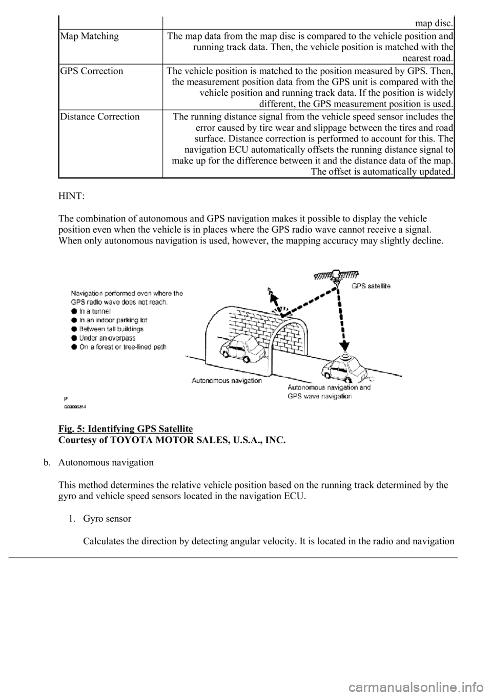
The combination of autonomous and GPS navigation makes it possible to display the vehicle
position even when the vehicle is in places where the GPS radio wave cannot receive a signal.
<003a004b00480051000300520051004f005c000300440058005700520051005200500052005800560003005100440059004c004a00440057004c005200510003004c005600030058005600480047000f0003004b0052005a0048005900480055000f000300
57004b004800030050004400530053004c0051004a00030044[ccuracy may slightly decline.
Fig. 5: Identifying GPS Satellite
Courtesy of TOYOTA MOTOR SALES, U.S.A., INC.
b. Autonomous navigation
This method determines the relative vehicle position based on the running track determined by the
gyro and vehicle speed sensors located in the navigation ECU.
1. Gyro sensor
Calculates the direction b
y detecting angular velocity. It is located in the radio and navigation
map disc.
Map MatchingThe map data from the map disc is compared to the vehicle position and
running track data. Then, the vehicle position is matched with the
nearest road.
GPS CorrectionThe vehicle position is matched to the position measured by GPS. Then,
the measurement position data from the GPS unit is compared with the
vehicle position and running track data. If the position is widely
different, the GPS measurement position is used.
Distance CorrectionThe running distance signal from the vehicle speed sensor includes the
error caused by tire wear and slippage between the tires and road
surface. Distance correction is performed to account for this. The
navigation ECU automatically offsets the running distance signal to
make up for the difference between it and the distance data of the map.
The offset is automatically updated.