Page 4204 of 4500
Fig. 12: Refrigerant Pressure With Manifold Gauge Set Chart (Insufficient Cooling)
Courtesy of TOYOTA MOTOR SALES, U.S.A., INC.
4. Poor circulation of refrigerant
Fig. 13: Identifying Poor Circulation Of Refrigerant
Courtesy of TOYOTA MOTOR SALES, U.S.A., INC.
Fig. 14: Refrigerant Pressure With Manifold Gauge Set Chart (Poor Circulation Of
Refrigerant)
Courtesy of TOYOTA MOTOR SALES, U.S.A., INC.
5. Refri
gerant does not circulate
Page 4205 of 4500
Fig. 15: Identifying Refrigerant Does Not Circulate
Courtesy of TOYOTA MOTOR SALES, U.S.A., INC.
Fig. 16: Refrigerant Pressure With Manifold Gauge Set Chart (Refrigerant Does Not
Circulate)
Courtesy of TOYOTA MOTOR SALES, U.S.A., INC.
6. Refri
gerant is overcharged or cooling effectiveness of condenser is insufficient
Page 4206 of 4500
Fig. 17: Identifying Refrigerant Is Overcharged Or Cooling Effectiveness Of Condenser Is
Insufficient
Courtesy of TOYOTA MOTOR SALES, U.S.A., INC.
Fig. 18: Refrigerant Pressure With Manifold Gauge Set Charge Chart (Refrigerant
Overcharged Or Cooling Effectiveness Of Condenser Is Insufficient)
Courtesy of TOYOTA MOTOR SALES, U.S.A., INC.
7. Air present in refrigeration system
Fig. 19: Identifying Air Present In Refrigeration System
Courtesy of TOYOTA MOTOR SALES, U.S.A., INC.
Page 4207 of 4500
Fig. 20: Refrigerant Pressure With Manifold Gauge Set Charge Chart (Air Present In
Refrigeration System)
Courtesy of TOYOTA MOTOR SALES, U.S.A., INC.
8. Expansion valve malfunction
Fig. 21: Identifying Expansion Valve Malfunction
Courtesy of TOYOTA MOTOR SALES, U.S.A., INC.
Fig. 22: Refrigerant Pressure With Manifold Gauge Set Charge Chart (Expansion Valve
Malfunction)
Courtesy of TOYOTA MOTOR SALES, U.S.A., INC.
9. Defective compression compressor
Page 4208 of 4500
Fig. 23: Identifying Defective Compression Compressor
Courtesy of TOYOTA MOTOR SALES, U.S.A., INC.
<0029004c004a0011000300150017001d00030035004800490055004c004a004800550044005100570003003300550048005600560058005500480003003a004c0057004b0003003000440051004c00490052004f00470003002a00440058004a0048000300
360048005700030026004b00440055004a004800030026004b[art (Defective
Compression Compressor)
Courtesy of TOYOTA MOTOR SALES, U.S.A., INC.
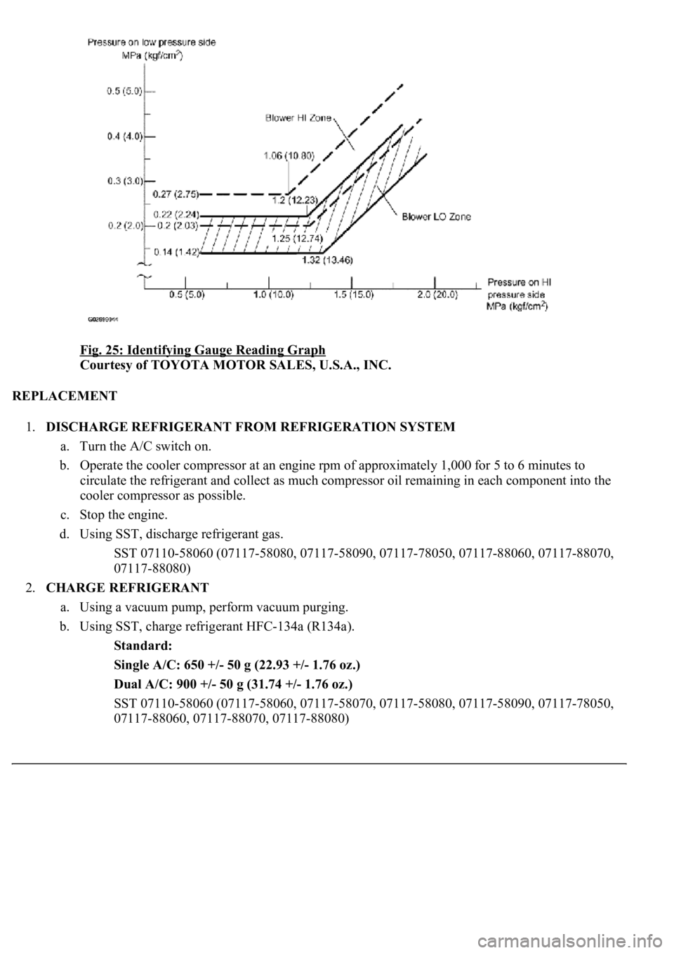
Gauge reading (Reference)
Page 4209 of 4500

Fig. 25: Identifying Gauge Reading Graph
Courtesy of TOYOTA MOTOR SALES, U.S.A., INC.
REPLACEMENT
1.DISCHARGE REFRIGERANT FROM REFRIGERATION SYSTEM
a. Turn the A/C switch on.
b. Operate the cooler compressor at an engine rpm of approximately 1,000 for 5 to 6 minutes to
circulate the refrigerant and collect as much compressor oil remaining in each component into the
cooler compressor as possible.
c. Stop the engine.
d. Using SST, discharge refrigerant gas.
<00360036003700030013001a00140014001300100018001b0013001900130003000b0013001a00140014001a00100018001b0013001b0013000f00030013001a00140014001a00100018001b0013001c0013000f00030013001a00140014001a0010001a00
1b001300180013000f00030013001a00140014001a0010001b[8060, 07117-88070,
07117-88080)
2.CHARGE REFRIGERANT
a. Using a vacuum pump, perform vacuum purging.
b. Using SST, charge refrigerant HFC-134a (R134a).
Standard:
Single A/C: 650 +/- 50 g (22.93 +/- 1.76 oz.)
Dual A/C: 900 +/- 50 g (31.74 +/- 1.76 oz.)
<00360036003700030013001a00140014001300100018001b0013001900130003000b0013001a00140014001a00100018001b001300190013000f00030013001a00140014001a00100018001b0013001a0013000f00030013001a00140014001a0010001800
1b0013001b0013000f00030013001a00140014001a00100018[8090, 07117-78050,
07117-88060, 07117-88070, 07117-88080)
Page 4213 of 4500
Fig. 29: Identifying Refrigerant Line Components And Replacements (Single A/C)
Courtesy of TOYOTA MOTOR SALES, U.S.A., INC.
Page 4215 of 4500
Fig. 30: Identifying Refrigerant Line Components And Replacements (Dual A/C)
Courtesy of TOYOTA MOTOR SALES, U.S.A., INC.
COMPONENTS