Page 350 of 1690

AVENSIS REPAIR MANUAL (RM1018E)
15. REMOVE CAMSHAFT
(a) Using several steps, loosen and rem")
A77309
15973
481062
A56228
A77413
Advance
Side Port
A31032
14±242
± ENGINE MECHANICALCAMSHAFT (1AZ±FSE)
AVENSIS REPAIR MANUAL (RM1018E)
15. REMOVE CAMSHAFT
(a) Using several steps, loosen and remove the 10 camshaft
bearing cap bolts uniformly in the sequence shown in the
illustration.
(b) Remove 5 camshaft bearings.
(c) Remove the camshaft.
(d) Tie the timing chain as shown in the illustration.
NOTICE:
�Be careful not to drop anything inside the timing
chain cover.
�Do not expose the chain to water, and prevents dust.
16. REMOVE CAMSHAFT TIMING GEAR ASSY
(a) Clamp the camshaft in a vise, and make sure the cam-
shaft timing gear does not rotate.
(b) Cover all the oil ports with vinyl tape except an advance
side port shown in the illustration.
(c) Put air pressure into the oil port with 150 kpa (1.5 kgf/cm
2
21 psi), and turn the camshaft timing gear to the advance
direction (counterclockwise) by hand.
CAUTION:
Cover the ports with shop rag to avoid oil splashing.
HINT:
Depending on the air pressure, the camshaft timing gear will
turn to the advance angle side without applying force by hand.
Also, under the condition that the pressure can be hardly ap-
plied because of the air leakage from the port, there may be the
case that the lock pin could be hardly released.
Page 351 of 1690

14±243
AVENSIS REPAIR MANUAL (RM1018E)
(d) Remove a fringe bolt")
A32639
A77414
Straight
Pin
Key
Groove
A77284
A77415Bearing Cap No. 1Bearing Cap No. 3 5
312 4
± ENGINE MECHANICALCAMSHAFT (1AZ±FSE)
14±243
AVENSIS REPAIR MANUAL (RM1018E)
(d) Remove a fringe bolt of camshaft timing gear.
NOTICE:
�Be sure not to remove the other 4 bolts.
�If reusing the camshaft timing gear, release the
straight pin lock first, and then install the gear.
17. INSTALL CAMSHAFT TIMING GEAR ASSY
(a) Put the camshaft timing gear and the camshaft together
with the straight pin off the key groove.
(b) Turn the camshaft timing gear assembly to the left direc-
tion (as shown in the illustration) while lightly pushing it to-
ward the camshaft. Push further at the position where the
pin gets into the groove.
NOTICE:
Be sure not to turn the camshaft timing gear to the retard
angle side (to the right direction).
(c) Check that there is no clearance between the gear's
fringe and the camshaft.
(d) Tighten the fringe bolt with the camshaft timing gear fixed.
Torque: 54 N�m (551 kgf�cm, 40 ft�lbf)
(e) Check that the camshaft timing gear can move to the re-
tard angle side (to the right direction), and is locked at the
most retarded position.
18. INSTALL CAMSHAFT
(a) Turn the crankshaft pulley, and align its groove with timing
mark 0 of the timing chain cover.
(b) Install the timing chain on the camshaft timing gear, with
the painted links aligned with the timing marks on the
camshaft timing gear.
(c) Examine the front marks and numbers and tighten the
bolts in the order shown in the illustration.
Torque:
Bearing cap No. 1 30 N�m (301 kgf�cm, 22 ft�lbf)
Bearing cap No. 3 9.0 N�m (92 kgf�cm, 80 in.�lbf)
19. INSTALL NO.2 CAMSHAFT
(a) Put the No. 2 camshaft on the cylinder head with the
painted links of chain aligned with the timing mark on the
camshaft timing gear.
Page 352 of 1690

AVENSIS REPAIR")
A52473
A77416
Bearing Cap No. 2 Bearing Cap No. 3
531 2 4
A77417
TightenHold
A77345
Timing
Marks
Timing
Marks
A77394
Raise
PinHook Push
14±244
± ENGINE MECHANICALCAMSHAFT (1AZ±FSE)
AVENSIS REPAIR MANUAL (RM1018E)
(b) Raising the No. 2 camshaft, tighten the set bolt temporari-
ly.
(c) Examine the from marks and numbers and tighten the
bolts in the sequence shown in the illustration.
Torque:
Bearing cap No. 2 30 N�m (301 kgf�cm, 22 ft�lbf)
Bearing cap No. 3 9.0 N�m (92 kgf�cm, 80 in.�lbf)
(d) Hold the camshaft with a wrench on the hexagonal lobe,
and tighten the camshaft timing gear set bolt.
Torque: 54 N�m (551 kgf�cm, 40 ft�lbf)
NOTICE:
Be careful not to damage the cylinder head and valve lifter.
(e) Check that the match marks on the timing chain and the
camshaft timing gears are positioned as shown in the il-
lustration
20. INSTALL CHAIN TENSIONER ASSY NO.1
(a) Release the ratchet pawl, fully push in the plunger and ap-
ply the hook to the pin so that the plunger is locked in posi-
tion.
Page 357 of 1690
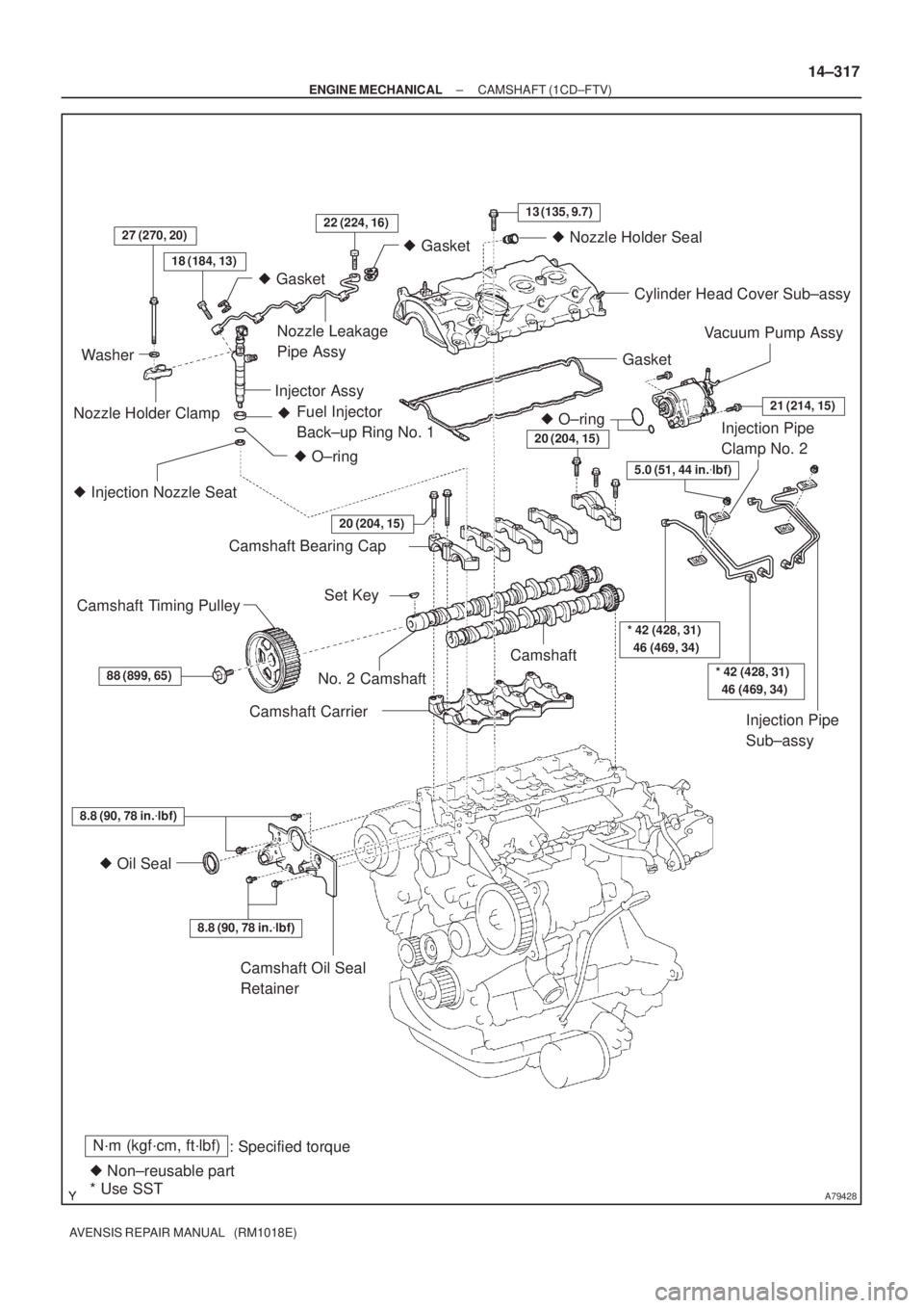
A79428
N´m (kgf´cm, ft´lbf)
: Specified torque
� Non±reusable part� Gasket
18 (184, 13)
27 (270, 20)22 (224, 16)13 (135, 9.7)
� Gasket
� O±ring Fuel Injector
Back±up Ring No. 1 �
� Injection Nozzle Seat
8.8 (90, 78 in.�lbf)
� Oil Seal
8.8 (90, 78 in.�lbf)
20 (204, 15)
Washer
Nozzle Holder ClampNozzle Leakage
Pipe Assy
Injector AssyCylinder Head Cover Sub±assy
Gasket
Camshaft Bearing Cap
No. 2 CamshaftCamshaft
Camshaft Carrier
Camshaft Oil Seal
Retainer
88 (899, 65)
Camshaft Timing PulleySet Key
20 (204, 15)
* 42 (428, 31)
46 (469, 34)
Injection Pipe
Clamp No. 2
Injection Pipe
Sub±assy � O±ring
21 (214, 15)
Vacuum Pump Assy
5.0 (51, 44 in.�lbf)
� Nozzle Holder Seal
* Use SST
* 42 (428, 31)
46 (469, 34)
± ENGINE MECHANICALCAMSHAFT (1CD±FTV)
14±317
AVENSIS REPAIR MANUAL (RM1018E)
Page 360 of 1690

AVENSIS REPAIR MANUAL (RM1018E)
33.REMOVE NOZZLE LEAKAGE PIPE ASSY (See page 11±60")
A09668
A09650
5
6
4 2
1
12 3
1011
13
8
7
15
14
9
A09619
SST
A09620
14±320
±
ENGINE MECHANICAL CAMSHAFT(1CD±FTV)
AVENSIS REPAIR MANUAL (RM1018E)
33.REMOVE NOZZLE LEAKAGE PIPE ASSY (See page 11±60)
34.REMOVE INJECTOR ASSY (See page 11±60)
HINT:
Since each injector assembly has a characteristic fuel injecting behavior, store them in correct order so that
they can be returned to the original locations when re±assembling. 35. REMOVE CAMSHAFT OIL SEAL RETAINER
(a) Remove the 4 bolts.
(b) Using a screwdriver, remove the oil seal retainer by pryingbetween the oil seal retainer and the camshaft bearing
cap.
36. REMOVE CAMSHAFT
(a) Using several steps, loosen and remove the 15 bearing cap bolts uniformly in the sequence shown in the illustra-
tion.
(b) Remove the 5 bearing caps and the camshaft sub±assy.
37. REMOVE NO.2 CAMSHAFT
(a) Remove the camshaft sub±assy and the camshaft carrier. 38. REMOVE CAMSHAFT OIL SEAL
(a) Using a screwdriver and a hammer, tap out the oil seal.
39. INSTALL CAMSHAFT OIL SEAL
(a) Using SST and a hammer, tap in a new oil seal until its sur-face is flush with the camshaft oil seal retainer edge.
SST 09223±46011
Page 361 of 1690

14±321
AVENSIS REPAIR MANUAL (RM1018E)
40. SET NO. 1 CYLINDER TO TDC/COMPRESSION
(a) Using t")
90�
A09683
TDC Mark
Dot Mark
A09624
A09625
A09626
Alignment Mark
± ENGINE MECHANICALCAMSHAFT (1CD±FTV)
14±321
AVENSIS REPAIR MANUAL (RM1018E)
40. SET NO. 1 CYLINDER TO TDC/COMPRESSION
(a) Using the crankshaft pulley bolt, turn the crankshaft to set
the dot mark of the crankshaft timing pulley at the position
of 90� BTDC.
NOTICE:
If the timing belt is disengaged, having the crankshaft tim-
ing pulley at wrong angle can cause the piston head and
valve head to come into contact with each other.
41. INSTALL CAMSHAFT
NOTICE:
Since the thrust clearance of the camshaft is small, the
camshaft must be kept level while it is being installed. If the
camshaft is not kept level, damage to the cylinder head or
the camshaft may result. To avoid this, the following proce-
dures should be carried out.
(a) Place the camshaft carrier on the cylinder head.
(b) Install the camshaft sub±assy No. 1.
(c) Apply engine oil to the cam and gear of the camshaft, and
the journal of the camshaft carrier.
(d) Place the intake camshaft on the camshaft carrier as
shown in the illustration so that the No. 3 and No. 4 of cyl-
inder cam lobes face downward.
42. INSTALL NO.2 CAMSHAFT
(a) Install the camshaft sub±assy No. 2.
(b) Apply engine oil to the cam and gear of the camshaft, and
the journal of the camshaft carrier.
(c) Engage the exhaust camshaft gear and the intake cam-
shaft gear by aligning the alignment marks on each gear.
(d) Roll down the exhaust camshaft onto the bearing journals
while engaging gears with each other.
Page 362 of 1690

AVENSIS REPAIR MANUAL (RM1018E)
(e)Insta")
A09601
Seal Packing
A09627
A09650
12
3
5
49
6
8
7
13
10
11
15
14 12
A09600
Seal Width
2 to 4 mm
Seal Packing
14±322
±
ENGINE MECHANICAL CAMSHAFT(1CD±FTV)
AVENSIS REPAIR MANUAL (RM1018E)
(e)Install the camshaft bearing caps. (1)Remove any oil packing (FIPG) material from theNo. 5 camshaft bearing cap.
(2)Apply seal packing to the No. 5 camshaft bearing cap as shown in the illustration.
Seal packing: Part No. 08826±00080 or equivalent
(3)Place the 5 bearing caps in their proper locations.
(4)Using several steps, install and tighten the 15 bear- ing cap bolts uniformly in the sequence shown in the
illustration.
Torque: 20 N �m (204 kgf �cm, 15 ft �lbf)
43.INSPECT VALVE CLEARANCE (See page 14±270)
44.ADJUST VALVE CLEARANCE (See page 14±270) 45. INSTALL CAMSHAFT OIL SEAL RETAINER
(a) Remove any old packing (FIPG) material and be carefulnot to drop any oil on the contact surfaces of the oil seal
retainer and the cylinder block.
(1) Thoroughly clean all components to remove all theloose material.
(2) Using non±residue solvent, clean both sealing sur- faces.
(b) Apply seal packing to the oil seal retainer as shown in the illustration.
Seal packing: Part No. 08826±00080 or equivalent
(1) Install a nozzle that has been cut to a 2 to 4 mm(0.08 to 0.16 in.) opening.
(2) Parts must be assembled within 15 minutes of ap- plication. Otherwise the material must be removed
and reapplied.
(3) Immediately remove nozzle from the tube and rein- stall the cap.
Page 369 of 1690
A64006
V±ribbed Belt
Tensioner Assy
Camshaft Bearing Cap No. 1
Camshaft Timing Gear
or Sprocket
Camshaft Timing Gear Assy
Chain Tensioner
Assy No. 1Camshaft Camshaft No. 2 Camshaft Bearing Cap No. 3
69 (704, 51)
29 (296, 21)
9.0 (92, 80 in.�lbf)
23 (235, 17)
54 (551, 40)
54 (551, 40)
13 (133, 10)
N´m (kgf´cm, ft´lbf) : Specified torque
Timing Chain Sub±assy
± ENGINE MECHANICALCAMSHAFT (1ZZ±FE/3ZZ±FE)
14±63
AVENSIS REPAIR MANUAL (RM1018E)