Page 373 of 1690
A62187
Hold
Tighten
A62188
24 5 3 1
A32124
A6218924 31
A32125
± ENGINE MECHANICALCAMSHAFT (1ZZ±FE/3ZZ±FE)
14±67
AVENSIS REPAIR MANUAL (RM1018E)
(d) Hold the camshaft with a wrench, loosen the camshaft
timing gear set bolt.
NOTICE:
Be careful not to damage the valve lifter.
(e) Using several steps, loosen the camshaft bearing cap
bolts on No. 2 camshaft in the sequence shown in the il-
lustration. Remove the bearing caps.
(f) Remove the camshaft timing gear as shown in the illustra-
tion.
(g) Using several steps, loosen the camshaft bearing cap
bolts on camshaft in the sequence shown in the illustra-
tion. Remove the bearing caps.
(h) Remove the camshaft as holding the timing chain.
Page 378 of 1690
A621983124 5 67
A62187
Hold
Tighten
A62185
Mark
Mark
Mark
Timing Chain
Cover Surface
Groove
A62177
Raise
Push
Hook
Pin
14±72
± ENGINE MECHANICALCAMSHAFT (1ZZ±FE/3ZZ±FE)
AVENSIS REPAIR MANUAL (RM1018E)
(e) Examine the front marks and numbers and tighten the
bolts in the sequence shown in the illustration.
Torque: 13 N�m (133 kgf�cm, 10 ft�lbf)
(f) Install the bearing cap No. 1.
Torque: 23 N�m (235 kgf�cm, 17 ft�lbf)
(g) Hold the camshaft with a wrench, tighten the camshaft
timing gear set bolt.
Torque: 54 N�m (551 kgf�cm, 40 ft�lbf)
NOTICE:
Be careful not to damage the valve lifter.
(h) Check that the match marks on the 2 camshaft sprockets
are aligned with each other and are aligned with the
painted links of the timing chain as shown in the illustra-
tion. Also, check the timing notch is aligned with the timing
mark º0º of the chain cover.
(i) Install chain tensioner.
(1) Check that the O±ring is clean, and set the hook as
shown in the illustration.
Page 388 of 1690

14±141
AVENSIS REPAIR MANUAL (RM1018E)
1")
A77283
A77284
A77285
Unleaded Gasoline
Timing
Marks
�eaded Gasoline
Timing
Marks
Timing
Marks
Timing
Marks
± ENGINE MECHANICALCHAIN SUB±ASSY (1AZ±FE)
14±141
AVENSIS REPAIR MANUAL (RM1018E)
19. REMOVE ENGINE SERVICE COVER BRACKET RH (RHD(W/ AIR CONDITIONER) STEERING
POSITION TYPE)
(a) Remove the bolt and the engine service cover bracket RH.
20. REMOVE IGNITION COIL ASSY
(a) Remove the 4 bolts and 4 ignition coils.
21. REMOVE CYLINDER HEAD COVER SUB±ASSY
(a) Disconnect the 2 PCV hoses from the cylinder head cov-
er.
(b) Remove the 8 bolts and 2 nuts, and then remove the cylin-
der head cover and gasket.
22. SET NO. 1 CYLINDER TO TDC/COMPRESSION
(a) Turn the crankshaft pulley, and align its timing notch with
timing mark 0 of the timing chain cover.
(b) Check that the timing marks of the camshaft timing gear
are aligned with the timing marks located on the No. 1 and
No. 2 bearing caps as shown in the illustration.
If not, turn the crankshaft 1 revolution (360�) and align the
marks as above.
Page 394 of 1690
A77285
Unleaded Gasoline
Timing
Marks
Leaded Gasoline
Timing
Marks
Timing
Marks
Timing
Marks
A52505
A77388
SST
± ENGINE MECHANICALCHAIN SUB±ASSY (1AZ±FE)
14±147
AVENSIS REPAIR MANUAL (RM1018E)
39. INSTALL CRANKSHAFT TIMING GEAR OR SPROCKET
40. SET NO. 1 CYLINDER TO TDC/COMPRESSION
(a) Turn the camshafts with a wrench on the hexagonal lobe,
and align the timing marks of the camshaft timing gear
with each timing mark located on the No. 1 and No. 2
bearing caps as shown in the illustration.
(b) Using the crankshaft pulley bolt, turn the crankshaft and
position the key on the crankshaft upward.
41. INSTALL CHAIN VIBRATION DAMPER NO.1
42. INSTALL CHAIN SUB±ASSY
Page 402 of 1690

14±141
AVENSIS REPAIR MANUAL (RM1018E)
1")
A77283
A77284
A77285
Unleaded Gasoline
Timing
Marks
�eaded Gasoline
Timing
Marks
Timing
Marks
Timing
Marks
± ENGINE MECHANICALCHAIN SUB±ASSY (1AZ±FE)
14±141
AVENSIS REPAIR MANUAL (RM1018E)
19. REMOVE ENGINE SERVICE COVER BRACKET RH (RHD(W/ AIR CONDITIONER) STEERING
POSITION TYPE)
(a) Remove the bolt and the engine service cover bracket RH.
20. REMOVE IGNITION COIL ASSY
(a) Remove the 4 bolts and 4 ignition coils.
21. REMOVE CYLINDER HEAD COVER SUB±ASSY
(a) Disconnect the 2 PCV hoses from the cylinder head cov-
er.
(b) Remove the 8 bolts and 2 nuts, and then remove the cylin-
der head cover and gasket.
22. SET NO. 1 CYLINDER TO TDC/COMPRESSION
(a) Turn the crankshaft pulley, and align its timing notch with
timing mark 0 of the timing chain cover.
(b) Check that the timing marks of the camshaft timing gear
are aligned with the timing marks located on the No. 1 and
No. 2 bearing caps as shown in the illustration.
If not, turn the crankshaft 1 revolution (360�) and align the
marks as above.
Page 408 of 1690
A77285
Unleaded Gasoline
Timing
Marks
Leaded Gasoline
Timing
Marks
Timing
Marks
Timing
Marks
A52505
A77388
SST
± ENGINE MECHANICALCHAIN SUB±ASSY (1AZ±FE)
14±147
AVENSIS REPAIR MANUAL (RM1018E)
39. INSTALL CRANKSHAFT TIMING GEAR OR SPROCKET
40. SET NO. 1 CYLINDER TO TDC/COMPRESSION
(a) Turn the camshafts with a wrench on the hexagonal lobe,
and align the timing marks of the camshaft timing gear
with each timing mark located on the No. 1 and No. 2
bearing caps as shown in the illustration.
(b) Using the crankshaft pulley bolt, turn the crankshaft and
position the key on the crankshaft upward.
41. INSTALL CHAIN VIBRATION DAMPER NO.1
42. INSTALL CHAIN SUB±ASSY
Page 431 of 1690
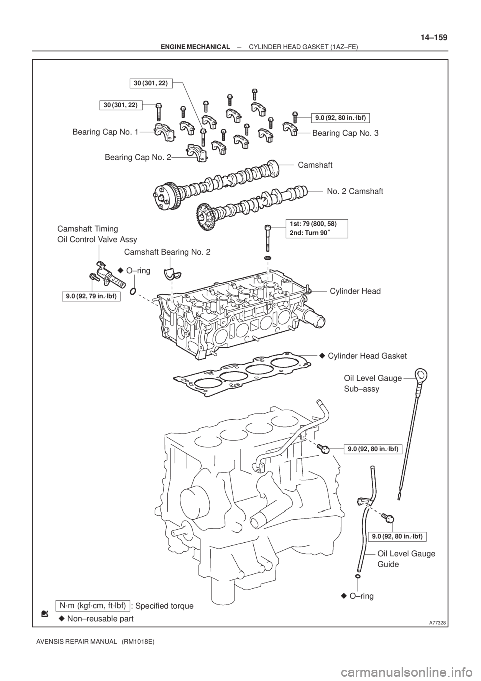
A77328
N´m (kgf´cm, ft´lbf)
: Specified torque
� Non±reusable part
30 (301, 22)
� O±ring
Bearing Cap No. 1
Bearing Cap No. 2
9.0 (92, 80 in.�lbf)
Bearing Cap No. 3
Camshaft
No. 2 Camshaft
Camshaft Bearing No. 2
Camshaft Timing
Oil Control Valve Assy
Cylinder Head
� Cylinder Head Gasket
9.0 (92, 80 in.�lbf)
Oil Level Gauge
Sub±assy
9.0 (92, 80 in.�lbf)
� O±ring
Oil Level Gauge
Guide
1st: 79 (800, 58)
2nd: Turn 90�
30 (301, 22)
9.0 (92, 79 in.�lbf)
± ENGINE MECHANICALCYLINDER HEAD GASKET (1AZ±FE)
14±159
AVENSIS REPAIR MANUAL (RM1018E)
Page 436 of 1690

AVENSIS REPAIR MANUAL (RM1018E)
53. REMOVE CAMSHAFT BEARING NO.2
54. SUPPORT EN")
A32664
A56213
A7740612 3
4 109
8 56 7
A77407
Overall Length 14±164
± ENGINE MECHANICALCYLINDER HEAD GASKET (1AZ±FE)
AVENSIS REPAIR MANUAL (RM1018E)
53. REMOVE CAMSHAFT BEARING NO.2
54. SUPPORT ENGINE ASSEMBLY WITH TRANSAXLE
(a) Install the oil pan sub±assy.
(b) Set the jack under the engine assembly w/ transaxle, and
place a wooden block on the jack.
(c) Remove the chain block and sling devise.
55. REMOVE CYLINDER HEAD SUB±ASSY
(a) Using several steps, loosen the 10 cylinder head bolts,
with 10 mm bi±hexagon wrench uniformly in the se-
quence shown in the illustration.
(b) Remove the 10 cylinder head bolts and plate washers.
NOTICE:
�Be careful not to drop washers into the cylinder head.
�Head warpage or cranking could result from remov-
ing bolts and installing in incorrect order.
56. REMOVE CYLINDER HEAD GASKET
57. INSPECT CYLINDER HEAD SET BOLT
(a) Using a vernier calipers, measure the length of the cylin-
der head set bolts from the seat to the end.
Standard bolt length:
161.3 to 162.3 mm (6.350 to 6.390 in.)
Maximum bolt length: 164.2 mm (6.465 in.)
If the length is greater than maximum, replace the cylinder head
set bolts.

14±67
AVENSIS REPAIR MANUAL (RM1018E)
(d) Hold the camshaft with a wrench, loosen the ca")

AVENSIS REPAIR MANUAL (R")

14±147
AVENSIS REPAIR MANUAL (RM1018")

14±147
AVENSIS REPAIR MANUAL (RM1018")