Page 444 of 1690
A77350
A52497
A32664
A56213
14±258
±
ENGINE MECHANICAL CYLINDER HEAD GASKET(1AZ±FSE)
AVENSIS REPAIR MANUAL (RM1018E)
53.REMOVE EXHAUST MANIFOLD CONVERTER SUB±ASSY
(a)Remove the 2 bolts and 2 nuts, and then detach the No.
1 and No. 2 exhaust manifold stay.
(b)Disconnect the 3 oxygen sensor connectors.
(c)Remove the 5 nuts, the exhaust manifold and gasket.
54.REMOVE NO.2 CAMSHAFT (See page 14±240)
55.REMOVE CAMSHAFT (See page 14±240)
56. REMOVE CAMSHAFT TIMING OIL CONTROL VALVE ASSY
(a) Remove the bolt and the oil control valve. 57. REMOVE CAMSHAFT BEARING NO.2
58. SUPPORT ENGINE ASSEMBLY WITH TRANSAXLE
(a) Install the oil pan sub±assy.
(b) Set the jack under the engine assembly w/ transaxle, andplace a wooden block on the jack.
(c) Remove the chain block and sling devise.
Page 454 of 1690
A79432
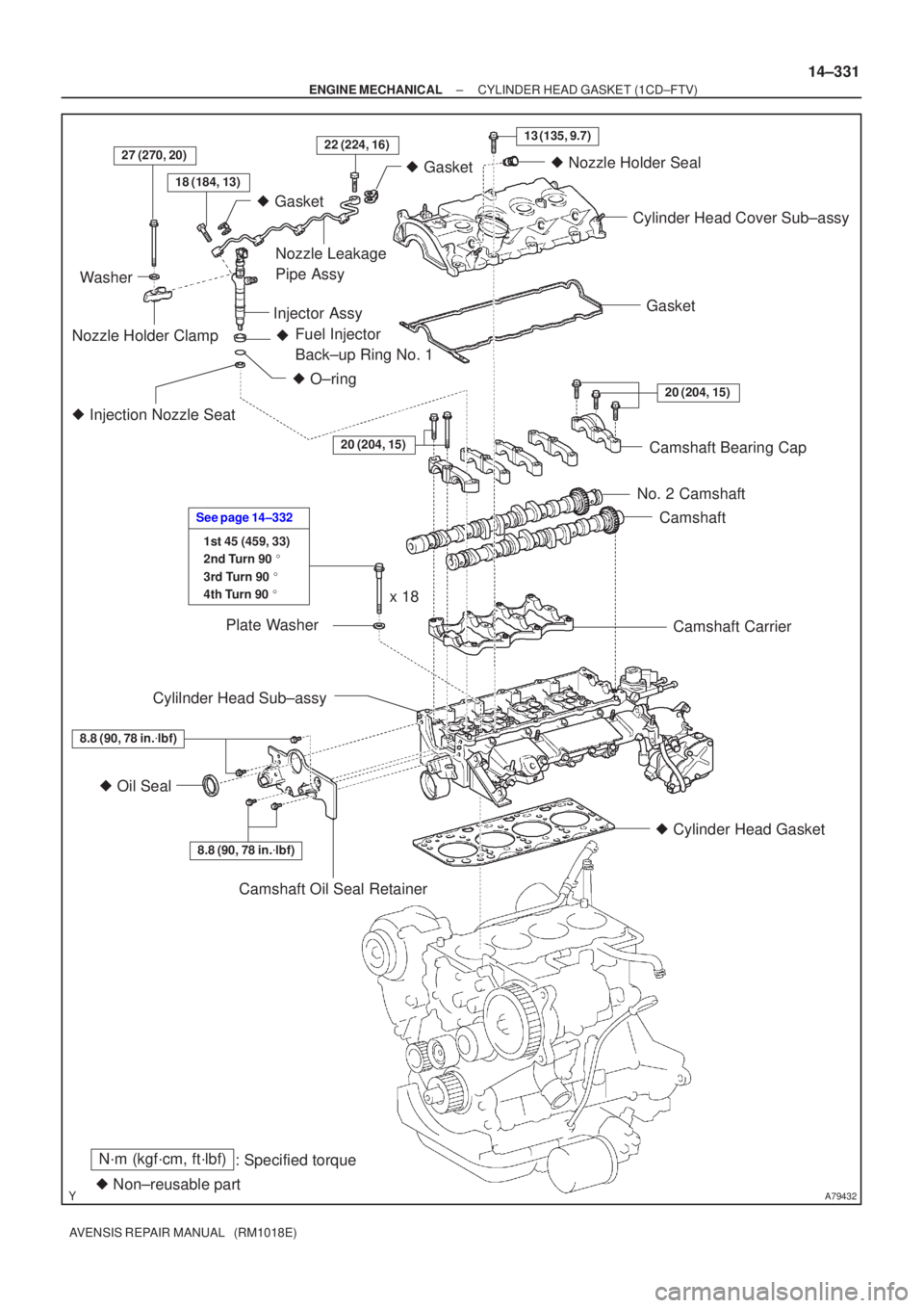
N´m (kgf´cm, ft´lbf): Specified torque
� Non±reusable part �
Gasket
18 (184, 13)
27 (270, 20)22 (224, 16)13 (135, 9.7)
� Gasket
� O±ring
Fuel Injector
Back±up Ring No. 1
�
� Injection Nozzle Seat
20 (204, 15)
8.8 (90, 78 in. �lbf)
� Oil Seal
8.8 (90, 78 in. �lbf)
1st 45 (459, 33)
2nd Turn 90 �
3rd Turn 90 �
4th Turn 90 �
See page 14±332
20 (204, 15)
Washer
Nozzle Holder Clamp Nozzle Leakage
Pipe Assy
Injector Assy �
Nozzle Holder Seal
Cylinder Head Cover Sub±assy
Gasket
Camshaft Bearing Cap
No. 2 Camshaft Camshaft
Camshaft Carrier
� Cylinder Head Gasket
Camshaft Oil Seal Retainer
Cylilnder Head Sub±assy
Plate Washer
x 18
±
ENGINE MECHANICAL CYLINDER HEAD GASKET (1CD±FTV)
14±331
AVENSIS REPAIR MANUAL (RM1018E)
Page 469 of 1690
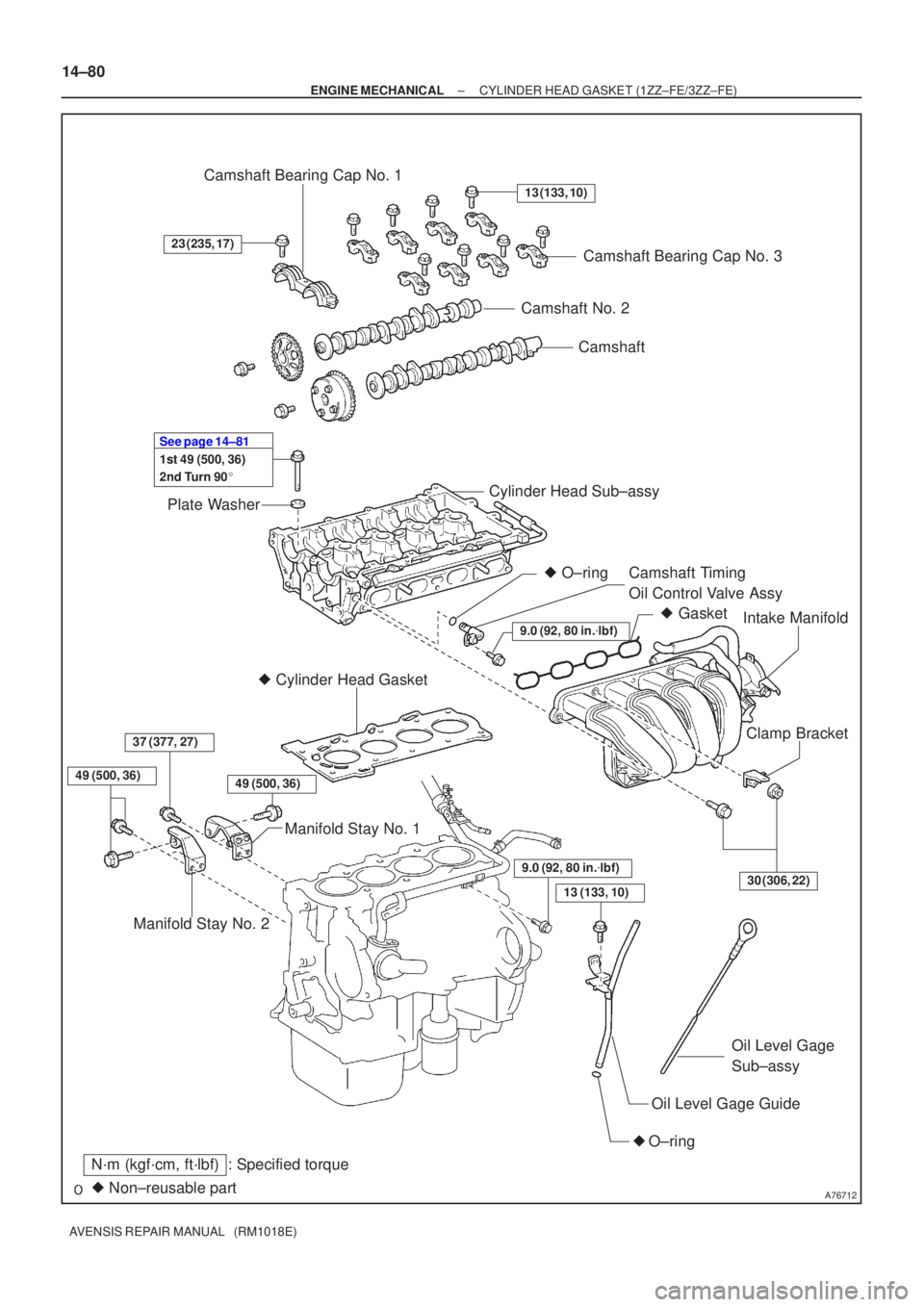
A76712
Camshaft
Camshaft No. 2
Plate Washer Camshaft Bearing Cap No. 1
Camshaft Bearing Cap No. 3
Cylinder Head Sub±assy Camshaft Timing
Oil Control Valve Assy
� Cylinder Head Gasket
Manifold Stay No. 1 Intake Manifold
Clamp Bracket
Oil Level Gage Guide
� O±ring Oil Level Gage
Sub±assy
�
Non±reusable part
N´m (kgf´cm, ft´lbf): Specified torque
13 (133, 10)
23 (235, 17)
30 (306, 22)
9.0 (92, 80 in. �lbf)
1st 49 (500, 36)
2nd Turn 90 �
See page 14±81
49 (500, 36)
�
Gasket
Manifold Stay No. 2
37 (377, 27)
� O±ring
9.0 (92, 80 in. �lbf)
13 (133, 10)
49 (500, 36)
14±80
±
ENGINE MECHANICAL CYLINDER HEAD GASKET (1ZZ±FE/3ZZ±FE)
AVENSIS REPAIR MANUAL (RM1018E)
Page 476 of 1690

14±87
AVENSIS REPAIR MANUAL (RM1018E)
46. REMOVE CHAIN")
A30857
A62814
4 2531
A62816
2
5 3
110 8 4 796
A62827
Lot No.
A62820
Overall Length
± ENGINE MECHANICALCYLINDER HEAD GASKET (1ZZ±FE/3ZZ±FE)
14±87
AVENSIS REPAIR MANUAL (RM1018E)
46. REMOVE CHAIN SUB±ASSY
(a) Remove the timing chain by prying the crankshaft timing
gear using screwdrivers as shown in the illustration.
NOTICE:
�Put shop rag to protect the engine.
�In case of revolving the camshafts with the chain off
the sprockets, turn the crankshaft 1/4 revolution
counterclockwise to prevent the valves from touch-
ing the pistons.
47. REMOVE CAMSHAFT
(a) Using several steps, loosen and remove the 19 bearing
cap bolts uniformly in the sequence shown in the illustra-
tion. Remove the 9 bearing caps, and both the intake and
exhaust camshafts.
48. REMOVE CYLINDER HEAD SUB±ASSY
(a) Using several steps, loosen and remove the 10 cylinder
head bolts with a 10 mm hexagon wrench uniformly in the
sequence shown in the illustration. Remove the 10 cylin-
der head bolts and 10 plate washers.
(b) Remove the cylinder head.
49. REMOVE CYLINDER HEAD GASKET
50. INSTALL CYLINDER HEAD GASKET
(a) Place a new cylinder head gasket on the cylinder block
with the Lot No. stamp facing upward.
NOTICE:
�Pay attention to the mounting orientation.
�Place the cylinder head on the gasket gently in order
not to damage the gasket with the bottom part of the
head.
51. INSPECT CYLINDER HEAD SET BOLT
(a) Using a vernier calipers, measure the length of cylinder
head bolt from the seat to the end.
Standard length: 146.8 to 148.2 mm (5.780 to 5.835 in.)
Maximum length: 148.5 mm (5.846 in.)
If the length exceeds the maximum, replace the bolt.
Page 477 of 1690

AVENSIS REPAI")
A62816
84 2 59
7 3 1 6 10
A62823
Paint Mark
90�
Front
A62150
Camshaft No. 2
Camshaft
A62825
62 4 8
51 3 7 11
10
9
A10079
14±88
± ENGINE MECHANICALCYLINDER HEAD GASKET (1ZZ±FE/3ZZ±FE)
AVENSIS REPAIR MANUAL (RM1018E)
52. INSTALL CYLINDER HEAD SUB±ASSY
HINT:
The cylinder head bolts are tightened in 2 successive steps.
(a) Apply a light coat of engine oil on the threads of the cylin-
der head bolts.
(b) Using several steps, install and tighten the 10 cylinder
head bolts and plate washers with a 10 mm hexagon
wrench uniformly in the sequence shown in the illustra-
tion.
Torque: 49 N�m (500 kgf�cm, 36 ft�lbf)
(c) Mark the front of the cylinder head bolt with paint.
(d) Retighten the cylinder head bolts 90� in the same se-
quence as step (b).
(e) Check that the paint mark of each bolt is at 90� angle to
the front.
53. INSTALL CAMSHAFT
(a) Apply a light coat of engine oil on the camshaft journals.
(b) Place the 2 camshafts on the cylinder head as shown in
the illustration.
(c) Examine the front marks and numbers and tighten the
bolts in the sequence shown in the illustration.
Torque:
23 N�m (235 kgf�cm, 17 ft�lbf) for Bearing cap No. 1
13 N�m (133 kgf�cm, 10 ft�lbf) for Bearing cap No. 3
54. INSTALL CHAIN SUB±ASSY
(a) Set No. 1 cylinder to TDC/compression.
(1) Turn the camshafts using a wrench to align the tim-
ing marks of the 2 camshaft timing sprockets.
Page 517 of 1690
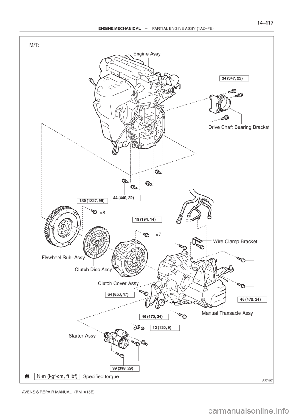
A77497
Engine Assy
Drive Shaft Bearing Bracket
Wire Clamp Bracket
Manual Transaxle Assy
Starter AssyClutch Disc Assy Flywheel Sub±Assy�8
�7
Clutch Cover Assy
N´m (kgf´cm, ft´lbf)
: Specified torque M/T:
34 (347, 25)
46 (470, 34)
13 (130, 9)
39 (398, 29)
64 (650, 47)
19 (194, 14)
44 (440, 32)
46 (470, 34)
130 (1327, 96)
± ENGINE MECHANICALPARTIAL ENGINE ASSY (1AZ±FE)
14±117
AVENSIS REPAIR MANUAL (RM1018E)
Page 518 of 1690
A77316
Engine Assy
Drive Shaft Bearing Bracket
Hole Plug
Drive Plate & Ring Gear
Sub±Assyx6
Wire Clamp Bracket
Starter Wire Starter Assy
34 (347, 25)
41 (420, 32)
98 (1,000, 72)
46 (469, 34)
13 (132, 10)
x8
N´m (kgf´cm, ft´lbf)
: Specified torque A/T:
Automatic Transaxle
46 (469, 34)
46 (469, 34)
37 (378, 27)
37 (378, 27)
64 (653, 47)
41 (418, 30)
14±118
± ENGINE MECHANICALPARTIAL ENGINE ASSY (1AZ±FE)
AVENSIS REPAIR MANUAL (RM1018E)
Page 528 of 1690

AVENSIS REPAIR MANUAL (RM1018E)
82.REMOVE EXHAUST MANIFOLD CONVERTER SUB±ASSY
(a)Remove the")
A60067
A52497
A32676
A78645
Oil Pressure Switch
14±128
±
ENGINE MECHANICAL PARTIAL ENGINE ASSY(1AZ±FE)
AVENSIS REPAIR MANUAL (RM1018E)
82.REMOVE EXHAUST MANIFOLD CONVERTER SUB±ASSY
(a)Remove the 3 bolts and 2 nuts, and then detach the No.
1 and No. 2 exhaust manifold stays.
(b)Remove the 5 nuts, and then remove the exhaust man- ifold converter and gasket.
83.REMOVE WATER INLET
(a)Remove the 2 nuts and the water inlet.
84.REMOVE THERMOSTAT
85.REMOVE IGNITION COIL ASSY
(a)Remove the 4 bolts and the 4 ignition coils. 86.REMOVE V±RIBBED BELT TENSIONER ASSY
(a)Remove the bolt and nut, and then remove the V±ribbedbelt tensioner.
87.REMOVE DRIVE SHAFT BEARING BRACKET
(a)Remove the 3 bolts and the drive shaft bearing bracket.
88.REMOVE FUEL DELIVERY PIPE W/INJECTOR (See page 11±26)
89. REMOVE WATER BY±PASS PIPE NO.1
(a) Remove the bolt and 2 nuts, and then detach the water by±pass pipe No\
. 1. 90. REMOVE ENGINE OIL PRESSURE SWITCH ASSY
(a) Using SST, remove the engine oil pressure switch.SST 09268±46021

AVENSIS REPAIR MANUAL (RM1018E)
53.REMOVE EXHAUST MANIFOLD CONVERTER SUB±ASSY
(a)Remove the 2 bolts and 2 nut")

41 (420, 32)
98 (1,000, 72)
46 (469, 34)
13 (132")