Page 189 of 1690

ON±VEHICLE INSPECTION
1. INSPECT FRONT AXLE HUB BEARIN")
3005B±02
D26919
D26920
C98714
C98715
30±2
± DRIVE SHAFT / PROPELLER SHAFTDRIVE SHAFT, PROPELLER SHAFT, AXLE
AVENSIS REPAIR MANUAL (RM1018E)
ON±VEHICLE INSPECTION
1. INSPECT FRONT AXLE HUB BEARING BACKLASH
(a) Using a dial indicator, check the backlash near the center
of the axle hub.
Maximum: 0.05 mm (0.0020 in.)
If the backlash exceeds the maximum, replace the bearing.
2. INSPECT FRONT AXLE HUB DEVIATION
(a) Using a dial indicator, check the deviation at the surface
of the axle hub outside the hub bolt.
Maximum: 0.05 mm (0.0020 in.)
If the backlash exceeds the maximum, replace the axle hub.
3. INSPECT REAR AXLE HUB BEARING BACKLASH
(a) Using a dial indicator, check the backlash near the center
of the axle hub.
Maximum: 0.05 mm (0.0020 in.)
If the backlash exceeds the maximum, replace the axle hub as-
sembly.
4. INSPECT REAR AXLE HUB DEVIATION
(a) Using a dial indicator, check the deviation at the surface
of the axle hub outside the hub bolt.
Maximum: 0.07 mm (0.0028 in.)
If the backlash exceeds the maximum, replace the axle hub as-
sembly.
Page 190 of 1690
30091±02
������D30592
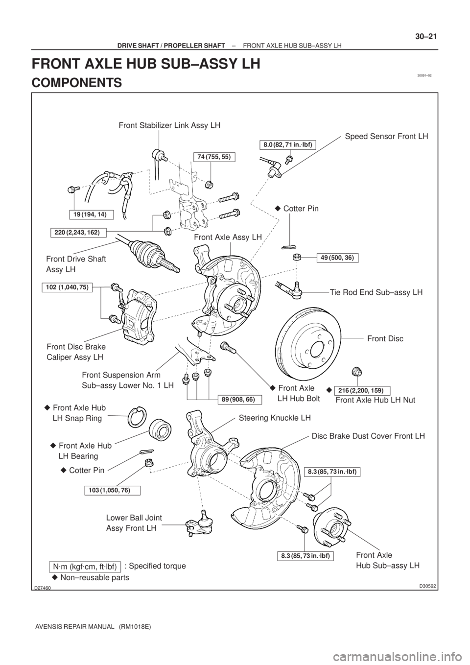
Speed Sensor Front LH
Lower Ball Joint
Assy Front LH
N�m (kgf�cm, ft�lbf): Specified torque
8.0 (82, 71 in.�lbf)
49 (500, 36)
Tie Rod End Sub±assy LH � Cotter Pin
Front Disc
Front Axle Assy LH
19 (194, 14)
Front Stabilizer Link Assy LH
74 (755, 55)
220 (2,243, 162)
Front Drive Shaft
Assy LH
Front Axle Hub LH Nut
216 (2,200, 159)�� Front Axle
LH Hub Bolt
89 (908, 66)
Steering Knuckle LH
Disc Brake Dust Cover Front LH
8.3 (85, 73 in.�lbf)
8.3 (85, 73 in.�lbf)Front Axle
Hub Sub±assy LH
Front Disc Brake
Caliper Assy LH
Front Suspension Arm
Sub±assy Lower No. 1 LH
� Front Axle Hub
LH Bearing
� Cotter Pin
103 (1,050, 76)
102 (1,040, 75)
� Non±reusable parts � Front Axle Hub
LH Snap Ring
± DRIVE SHAFT / PROPELLER SHAFTFRONT AXLE HUB SUB±ASSY LH
30±21
AVENSIS REPAIR MANUAL (RM1018E)
FRONT AXLE HUB SUB±ASSY LH
COMPONENTS
Page 193 of 1690
F40228
SST
F40229
F40156
SST
������F45153
Turn SST
SST Hold
30±24
± DRIVE SHAFT / PROPELLER SHAFTFRONT AXLE HUB SUB±ASSY LH
AVENSIS REPAIR MANUAL (RM1018E)
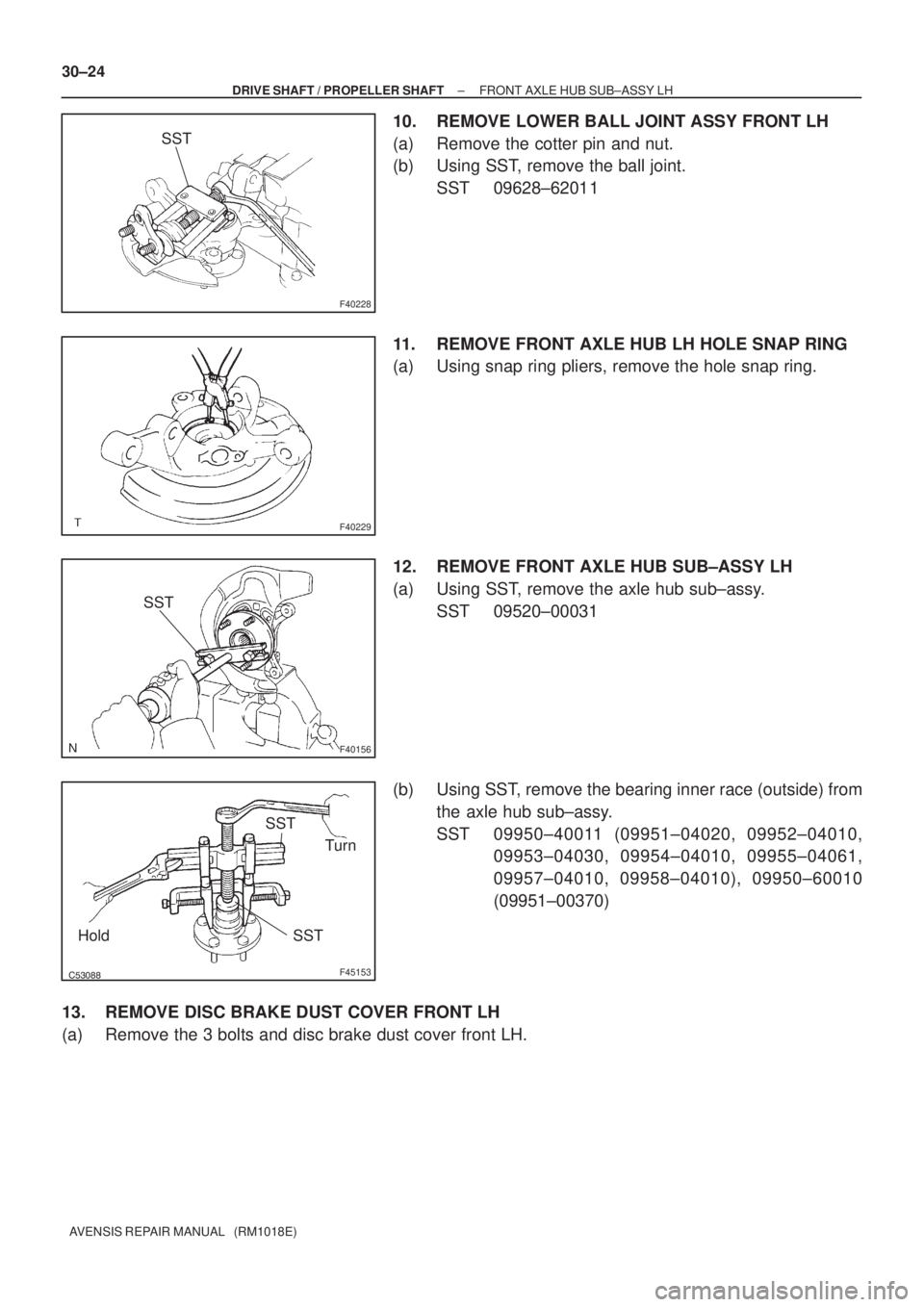
10. REMOVE LOWER BALL JOINT ASSY FRONT LH
(a) Remove the cotter pin and nut.
(b) Using SST, remove the ball joint.
SST 09628±62011
11. REMOVE FRONT AXLE HUB LH HOLE SNAP RING
(a) Using snap ring pliers, remove the hole snap ring.
12. REMOVE FRONT AXLE HUB SUB±ASSY LH
(a) Using SST, remove the axle hub sub±assy.
SST 09520±00031
(b) Using SST, remove the bearing inner race (outside) from
the axle hub sub±assy.
SST 09950±40011 (09951±04020, 09952±04010,
09953±04030, 09954±04010, 09955±04061,
09957±04010, 09958±04010), 09950±60010
(09951±00370)
13. REMOVE DISC BRAKE DUST COVER FRONT LH
(a) Remove the 3 bolts and disc brake dust cover front LH.
Page 194 of 1690

14. REMOVE FRONT AXLE HUB LH BEARING
(a) Place the")
F40230
SST
SST
F40231
SST
F40232
SST
SST
F40229
± DRIVE SHAFT / PROPELLER SHAFTFRONT AXLE HUB SUB±ASSY LH
30±25
AVENSIS REPAIR MANUAL (RM1018E)
14. REMOVE FRONT AXLE HUB LH BEARING
(a) Place the bearing inner race (outside) on the axle hub LH
bearing.
(b) Using SST and a press, remove the axle hub LH bearing
from the steering knuckle.
SST 09527±17011, 09950±60010 (09951±00640),
09950±70010 (09951±07100)
15. INSTALL FRONT AXLE HUB LH BEARING
(a) Using SST and a press, install a new axle hub LH bearing
to the steering knuckle.
SST 09950±60020 (09951±00720), 09950±70010
(09951±07100)
16. INSTALL DISC BRAKE DUST COVER FRONT LH
(a) Install the disc brake dust cover with the 3 bolts.
Torque: 8.3 N�m (85 kgf�cm, 73 in.�lbf)
17. INSTALL FRONT AXLE HUB SUB±ASSY LH
(a) Using SST and a press, install the axle hub sub±assy.
SST 09608±32010, 09950±60010 (09951±00600),
09950±70010 (09951±07100)
18. INSTALL FRONT AXLE HUB LH HOLE SNAP RING
(a) Using snap ring pliers, install the hole snap ring.
Page 196 of 1690

25. INSTALL FRONT DISC BRAKE CALIPER ASSY LH
(a) Install the disc brake calip")
C67088
F44775
C80291
±
DRIVE SHAFT / PROPELLER SHAFT FRONT AXLE HUB SUB±ASSY LH
30±27
AVENSIS REPAIR MANUAL (RM1018E)
25. INSTALL FRONT DISC BRAKE CALIPER ASSY LH
(a) Install the disc brake caliper assy with the 2 bolts to the
steering knuckle.
Torque: 104 N �m (1,040 kgf �cm, 75 ft �lbf)
26. INSTALL FRONT AXLE HUB LH NUT
(a) Using a socket wrench (30 mm), install a new axle hub LH nut. Torque: 216 N �m (2,200 kgf �cm, 159 ft �lbf)
27. SEPARATE FRONT DISC BRAKE CALIPER ASSY LH
(a) Removing the 2 bolts, separate the disc brake caliper assy from the stee\
ring knuckle.
NOTICE:
Use a string or other device to keep the brake caliper from hanging down\
.
28. REMOVE FRONT DISC
29.INSPECT BEARING BACKLASH (See page 30±2)
30.INSPECT AXLE HUB DEVIATION (See page 30±2)
31. INSTALL FRONT DISC
32. INSTALL FRONT DISC BRAKE CALIPER ASSY LH
(a) Install the disc brake caliper assy with the 2 bolts to the steering knu\
ckle. Torque: 104 N �m (1,040 kgf �cm, 75 ft �lbf)
33. CONNECT SPEED SENSOR FRONT LH
(a) Install the speed sensor front LH to the steering knuckle with the bolt.
Torque: 8.0 N �m (82 kgf �cm, 71 in. �lbf)
(b) Connect the speed sensor wire and flexible hose to the shock absorber with the bolt.
Torque: 19 N �m (194 kgf �cm, 14 ft �lbf)
NOTICE:
�Be careful not to damage the speed sensor.
�Keep the speed sensor clean.
�Do not twist the sensor wire when installing the sen-
sor.
Page 201 of 1690
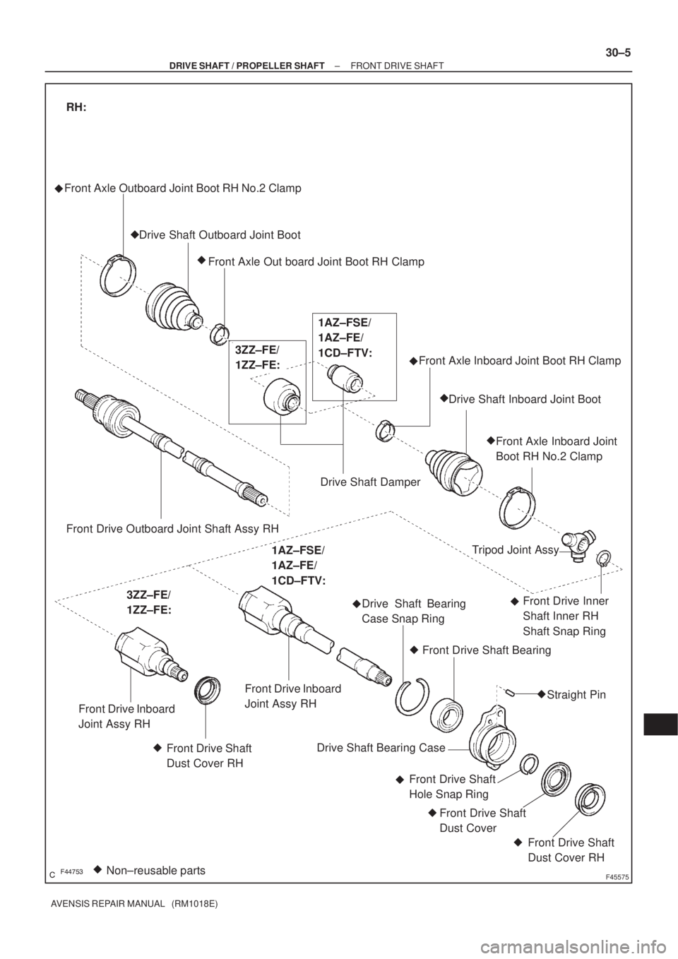
������F45575Non±reusable parts � Front Axle Outboard Joint Boot RH No.2 Clamp
Drive Shaft Outboard Joint Boot
Front Axle Out board Joint Boot RH Clamp
Drive Shaft DamperFront Axle Inboard Joint Boot RH Clamp
Drive Shaft Inboard Joint Boot
Front Axle Inboard Joint
Boot RH No.2 Clamp
�
�
Front Drive Outboard Joint Shaft Assy RH
RH:
3ZZ±FE/
1ZZ±FE:1AZ±FSE/
1AZ±FE/
1CD±FTV:
Front Drive Inboard
Joint Assy RH
Front Drive Shaft
Dust Cover RHTripod Joint Assy
Front Drive Inner
Shaft Inner RH
Shaft Snap Ring Drive Shaft Bearing
Case Snap Ring
Front Drive Shaft Bearing
Straight Pin
Drive Shaft Bearing Case
Front Drive Shaft
Hole Snap Ring
Front Drive Shaft
Dust Cover
Front Drive Shaft
Dust Cover RH �
�
� �
��
�
�
3ZZ±FE/
1ZZ±FE:
1AZ±FSE/
1AZ±FE/
1CD±FTV:
Front Drive Inboard
Joint Assy RH
�
�
�
�
± DRIVE SHAFT / PROPELLER SHAFTFRONT DRIVE SHAFT
30±5
AVENSIS REPAIR MANUAL (RM1018E)
Page 202 of 1690
30093±02
������F45576
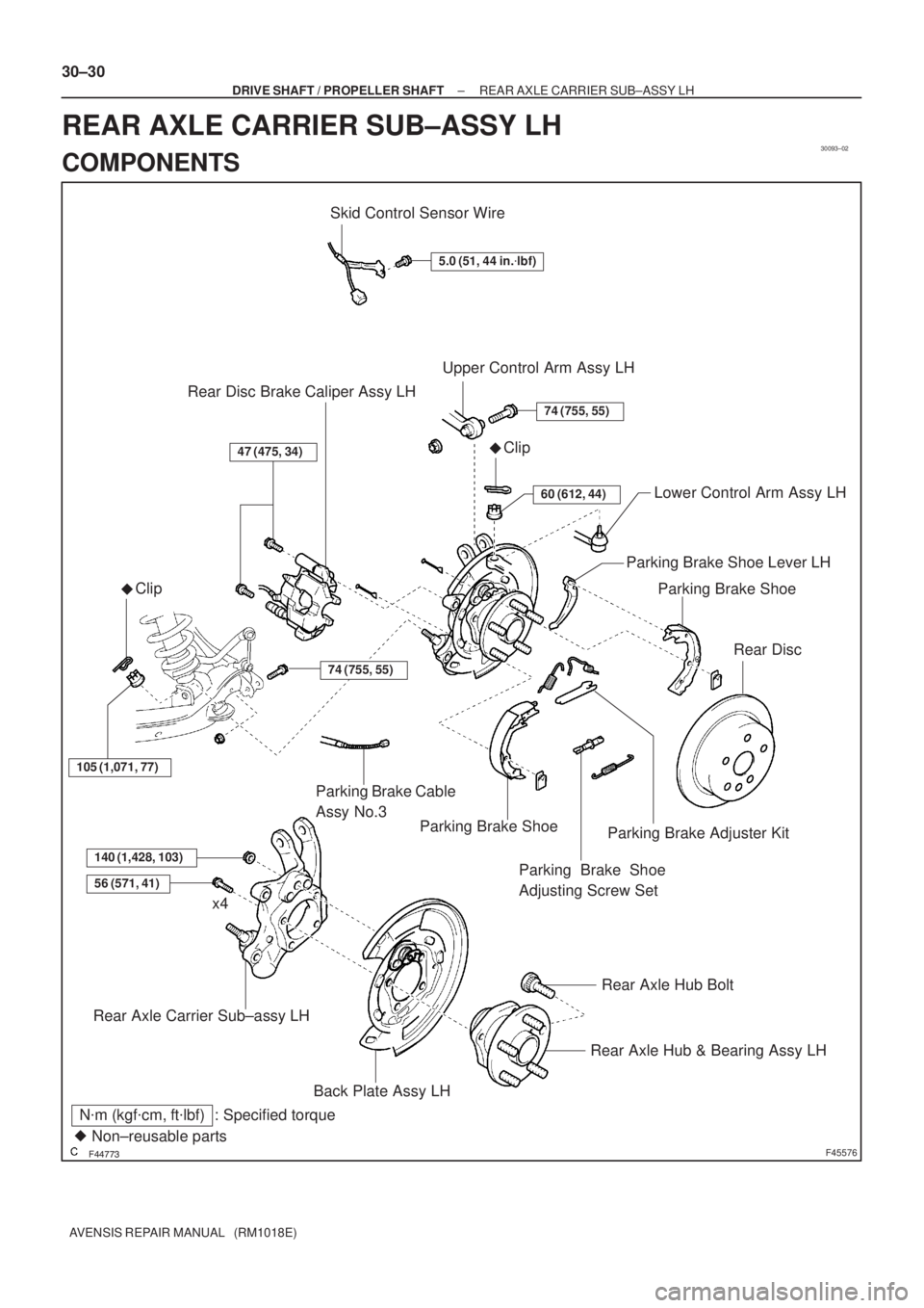
Skid Control Sensor Wire
5.0 (51, 44 in.�lbf)
Upper Control Arm Assy LH
�Clip
74 (755, 55)
60 (612, 44)Lower Control Arm Assy LH
Parking Brake Shoe
Rear Disc
47 (475, 34)
Rear Disc Brake Caliper Assy LH
�Clip
105 (1,071, 77)
Parking Brake Shoe
140 (1,428, 103)
56 (571, 41)
Rear Axle Carrier Sub±assy LH
Rear Axle Hub & Bearing Assy LH
Rear Axle Hub Bolt
x4
N�m (kgf�cm, ft�lbf) : Specified torque
� Non±reusable partsParking Brake Cable
Assy No.3
Parking Brake Shoe
Adjusting Screw Set
Parking Brake Adjuster Kit
Parking Brake Shoe Lever LH
74 (755, 55)
Back Plate Assy LH
30±30
± DRIVE SHAFT / PROPELLER SHAFTREAR AXLE CARRIER SUB±ASSY LH
AVENSIS REPAIR MANUAL (RM1018E)
REAR AXLE CARRIER SUB±ASSY LH
COMPONENTS
Page 204 of 1690
������F45753HoldTurn
SST
G21537
G21542
G20965
30±32
± DRIVE SHAFT / PROPELLER SHAFTREAR AXLE CARRIER SUB±ASSY LH
AVENSIS REPAIR MANUAL (RM1018E)
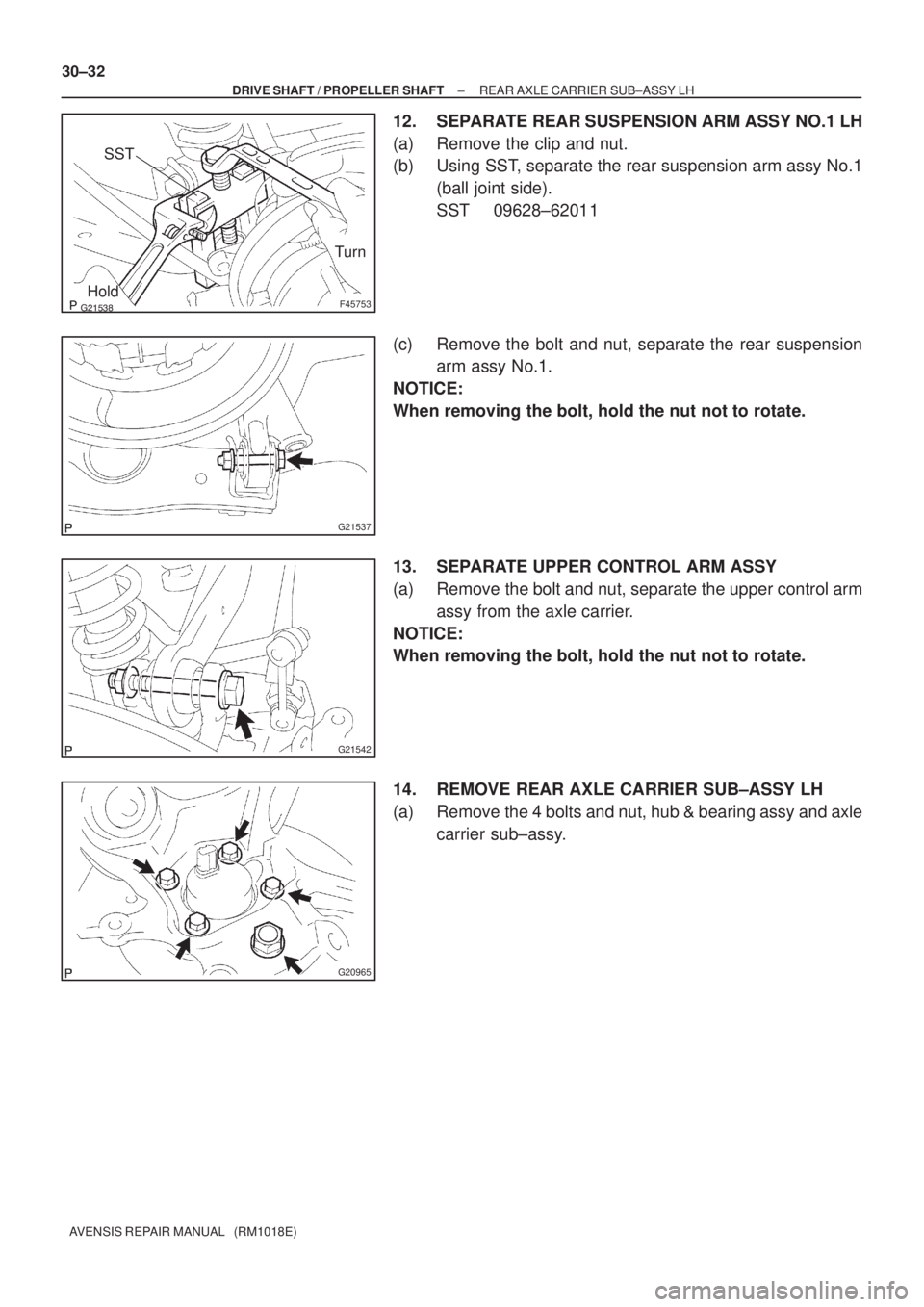
12. SEPARATE REAR SUSPENSION ARM ASSY NO.1 LH
(a) Remove the clip and nut.
(b) Using SST, separate the rear suspension arm assy No.1
(ball joint side).
SST 09628±62011
(c) Remove the bolt and nut, separate the rear suspension
arm assy No.1.
NOTICE:
When removing the bolt, hold the nut not to rotate.
13. SEPARATE UPPER CONTROL ARM ASSY
(a) Remove the bolt and nut, separate the upper control arm
assy from the axle carrier.
NOTICE:
When removing the bolt, hold the nut not to rotate.
14. REMOVE REAR AXLE CARRIER SUB±ASSY LH
(a) Remove the 4 bolts and nut, hub & bearing assy and axle
carrier sub±assy.