Page 126 of 1690
4200G±05
D26951
EXCEPT 1CD±FTV Engine Type:1CD±FTV Engine Type:
������D25280Matchmarks
42±26
±
CLUTCH CLUTCH UNIT (MTM)
AVENSIS REPAIR MANUAL (RM1018E)
OVERHAUL
1. REMOVE MANUAL TRANSAXLE ASSY
(a)1ZZ±FE, 3ZZ±FE Engine (See page 41±15)
(b)1AZ±FE, 1AZ±FSE Engine (See page 41±24)
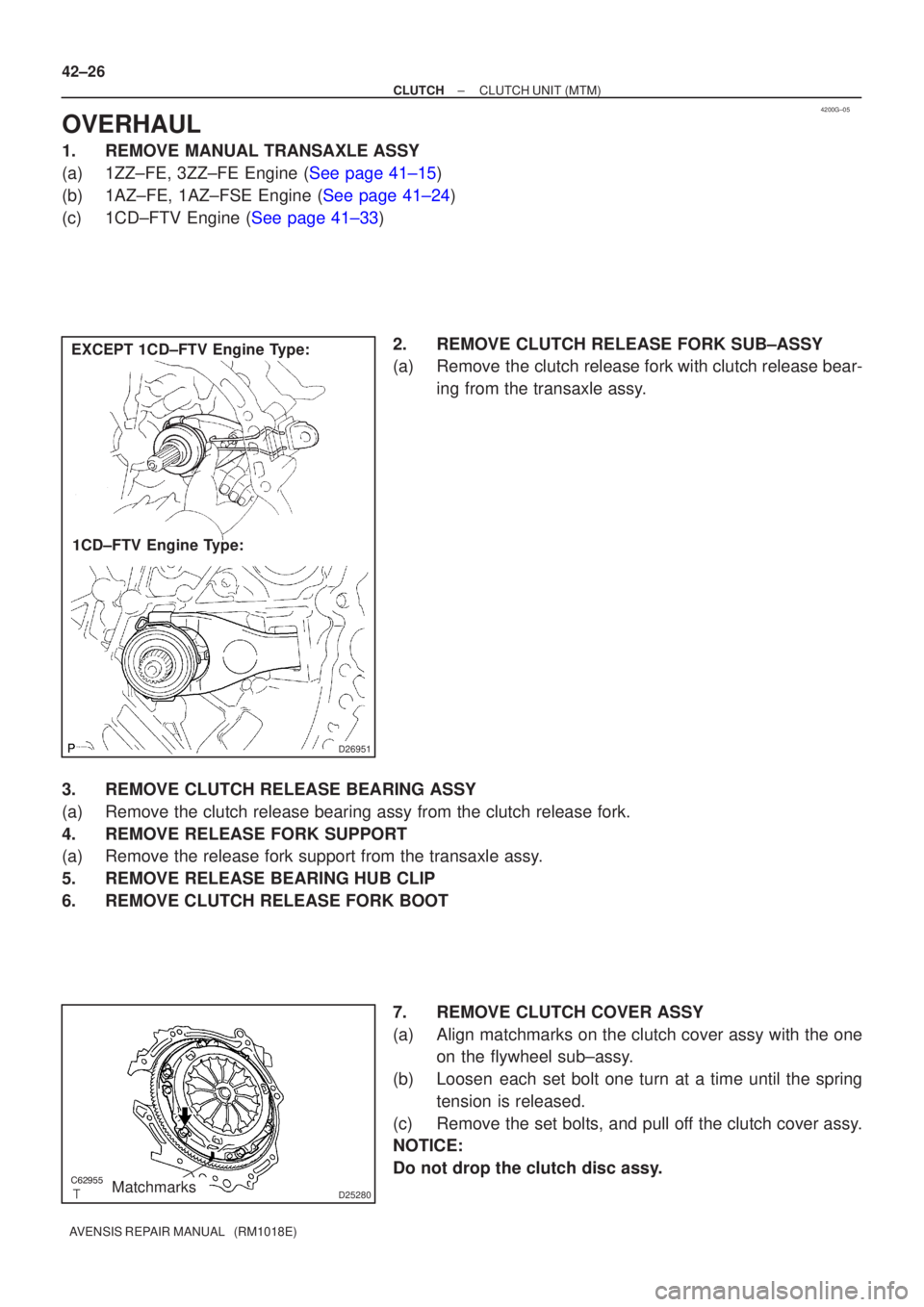
(c)1CD±FTV Engine (See page 41±33) 2. REMOVE CLUTCH RELEASE FORK SUB±ASSY
(a) Remove the clutch release fork with clutch release bear-ing from the transaxle assy.
3. REMOVE CLUTCH RELEASE BEARING ASSY
(a) Remove the clutch release bearing assy from the clutch release fork.
4. REMOVE RELEASE FORK SUPPORT
(a) Remove the release fork support from the transaxle assy.
5. REMOVE RELEASE BEARING HUB CLIP
6. REMOVE CLUTCH RELEASE FORK BOOT 7. REMOVE CLUTCH COVER ASSY
(a) Align matchmarks on the clutch cover assy with the oneon the flywheel sub±assy.
(b) Loosen each set bolt one turn at a time until the spring tension is released.
(c) Remove the set bolts, and pull off the clutch cover assy.
NOTICE:
Do not drop the clutch disc assy.
Page 128 of 1690
Q01060
D30059
1CD±FTV Engine Type: Others:
Flywheel Side
SST(s)
D26323
SST(s)
Matchmarks 7
1 (Temporally), 4
3
6
2.58
D00205
SST(s)
42±28
± CLUTCHCLUTCH UNIT (MTM)
AVENSIS REPAIR MANUAL (RM1018E)
12. INSPECT CLUTCH RELEASE BEARING ASSY
(a) Turn the release bearing by hand while applying force in
the axial direction.
HINT:
The bearing is permanently lubricated and requires no cleaning
or lubrication.
Replace the release bearing assy as necessary.
13. INSTALL CLUTCH DISC ASSY
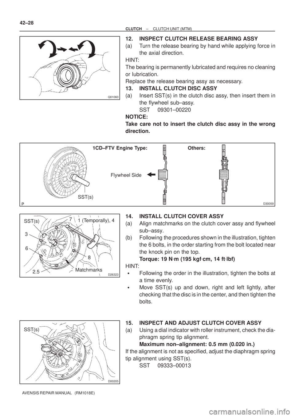
(a) Insert SST(s) in the clutch disc assy, then insert them in
the flywheel sub±assy.
SST 09301±00220
NOTICE:
Take care not to insert the clutch disc assy in the wrong
direction.
14. INSTALL CLUTCH COVER ASSY
(a) Align matchmarks on the clutch cover assy and flywheel
sub±assy.
(b) Following the procedures shown in the illustration, tighten
the 6 bolts, in the order starting from the bolt located near
the knock pin on the top.
Torque: 19 N�m (195 kgf�cm, 14 ft�lbf)
HINT:
�Following the order in the illustration, tighten the bolts at
a time evenly.
�Move SST(s) up and down, right and left lightly, after
checking that the disc is in the center, and then tighten the
bolts.
15. INSPECT AND ADJUST CLUTCH COVER ASSY
(a) Using a dial indicator with roller instrument, check the dia-
phragm spring tip alignment.
Maximum non±alignment: 0.5 mm (0.020 in.)
If the alignment is not as specified, adjust the diaphragm spring
tip alignment using SST(s).
SST 09333±00013
Page 129 of 1690
D26819
EXCEPT 1CD±FTV Engine Type:
1CD±FTV Engine Type:
Release Hub Grease
±
CLUTCH CLUTCH UNIT (MTM)
42±29
AVENSIS REPAIR MANUAL (RM1018E)
16. INSTALL RELEASE FORK SUPPORT
(a) Install the release fork support to the transaxle assy.
Torque:
1ZZ±FE/3ZZ±FE/1CD±FTV Engine Type: 37 N �m (375 kgf �cm, 27 ft �lbf)
1AZ±FSE/1AZ±FE Engine Type: 47 N �m (480 kgf �cm, 35 ft �lbf)
17. INSTALL RELEASE BEARING HUB CLIP
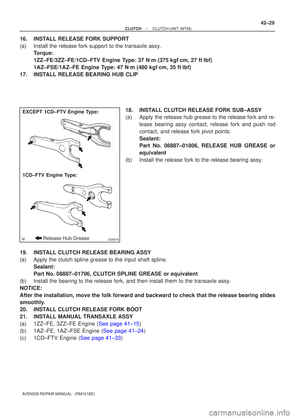
18. INSTALL CLUTCH RELEASE FORK SUB±ASSY
(a) Apply the release hub grease to the release fork and re-lease bearing assy contact, release fork and push rod
contact, and release fork pivot points.
Sealant:
Part No. 08887±01806, RELEASE HUB GREASE or
equivalent
(b) Install the release fork to the release bearing assy.
19. INSTALL CLUTCH RELEASE BEARING ASSY
(a) Apply the clutch spline grease to the input shaft spline. Sealant:
Part No. 08887±01706, CLUTCH SPLINE GREASE or equivalent
(b) Install the bearing to the release fork, and then install them to the tr\
ansaxle assy.
NOTICE:
After the installation, move the folk forward and backward to check that\
the release bearing slides
smoothly.
20. INSTALL CLUTCH RELEASE FORK BOOT
21. INSTALL MANUAL TRANSAXLE ASSY
(a)1ZZ±FE, 3ZZ±FE Engine (See page 41±15)
(b)1AZ±FE, 1AZ±FSE Engine (See page 41±24)
(c)1CD±FTV Engine (See page 41±33)
Page 149 of 1690
Radiator CapRadiator Cap Tester
30� or more
A51912
A36661
Turn 16±16
± COOLINGCOOLING SYSTEM (1AZ±FE)
AVENSIS REPAIR MANUAL (RM1018E)
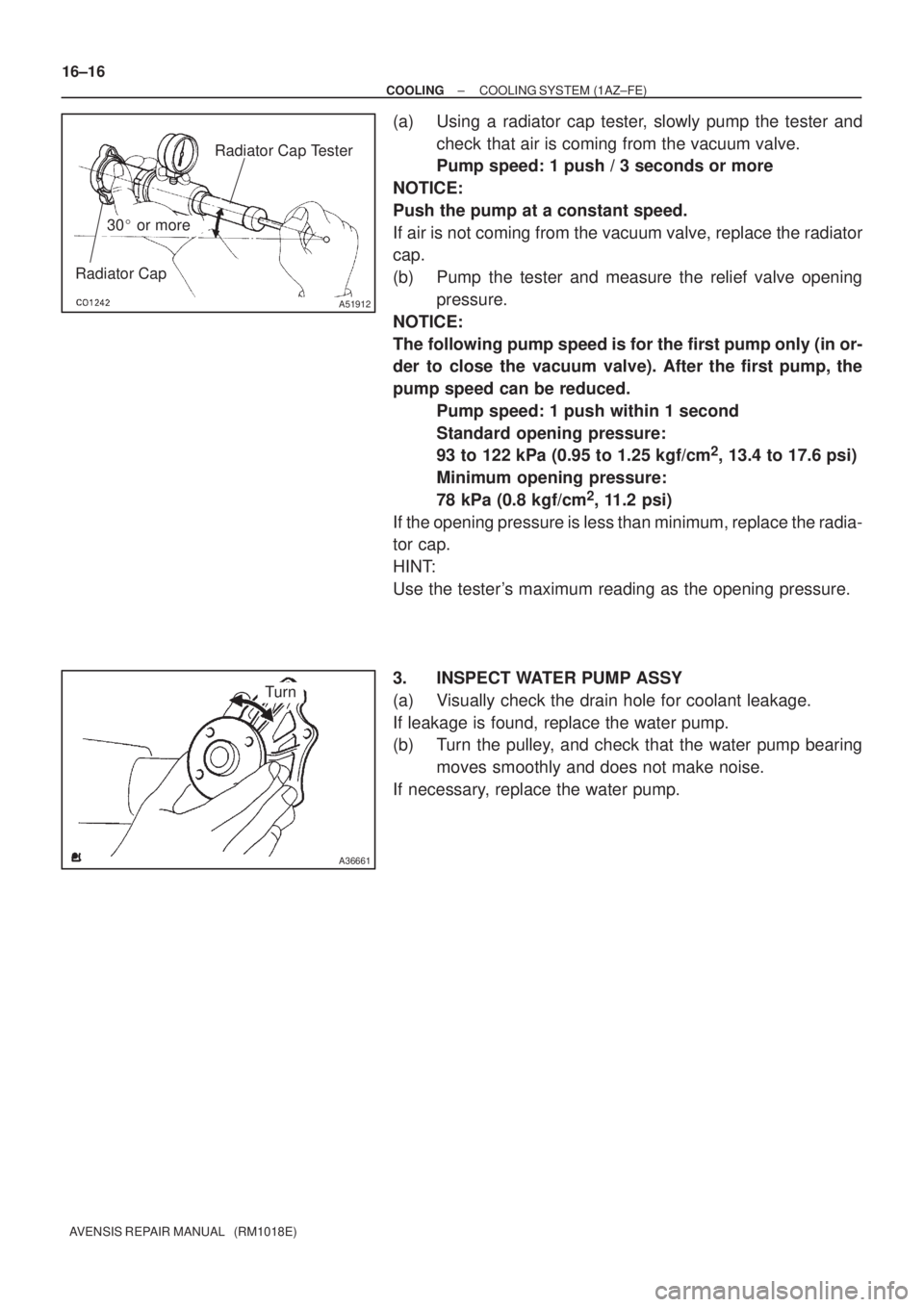
(a) Using a radiator cap tester, slowly pump the tester and
check that air is coming from the vacuum valve.
Pump speed: 1 push / 3 seconds or more
NOTICE:
Push the pump at a constant speed.
If air is not coming from the vacuum valve, replace the radiator
cap.
(b) Pump the tester and measure the relief valve opening
pressure.
NOTICE:
The following pump speed is for the first pump only (in or-
der to close the vacuum valve). After the first pump, the
pump speed can be reduced.
Pump speed: 1 push within 1 second
Standard opening pressure:
93 to 122 kPa (0.95 to 1.25 kgf/cm
2, 13.4 to 17.6 psi)
Minimum opening pressure:
78 kPa (0.8 kgf/cm
2, 11.2 psi)
If the opening pressure is less than minimum, replace the radia-
tor cap.
HINT:
Use the tester's maximum reading as the opening pressure.
3. INSPECT WATER PUMP ASSY
(a) Visually check the drain hole for coolant leakage.
If leakage is found, replace the water pump.
(b) Turn the pulley, and check that the water pump bearing
moves smoothly and does not make noise.
If necessary, replace the water pump.
Page 153 of 1690
Radiator CapRadiator Cap Tester
30� or more
A51912
A36661
Turn 16±28
± COOLINGCOOLING SYSTEM (1AZ±FSE)
AVENSIS REPAIR MANUAL (RM1018E)
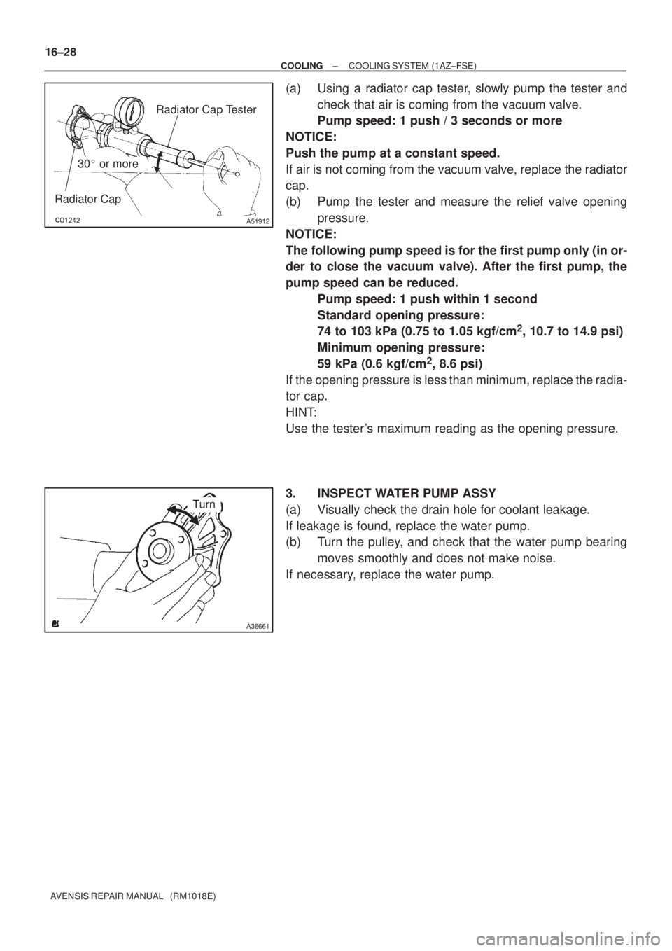
(a) Using a radiator cap tester, slowly pump the tester and
check that air is coming from the vacuum valve.
Pump speed: 1 push / 3 seconds or more
NOTICE:
Push the pump at a constant speed.
If air is not coming from the vacuum valve, replace the radiator
cap.
(b) Pump the tester and measure the relief valve opening
pressure.
NOTICE:
The following pump speed is for the first pump only (in or-
der to close the vacuum valve). After the first pump, the
pump speed can be reduced.
Pump speed: 1 push within 1 second
Standard opening pressure:
74 to 103 kPa (0.75 to 1.05 kgf/cm
2, 10.7 to 14.9 psi)
Minimum opening pressure:
59 kPa (0.6 kgf/cm
2, 8.6 psi)
If the opening pressure is less than minimum, replace the radia-
tor cap.
HINT:
Use the tester's maximum reading as the opening pressure.
3. INSPECT WATER PUMP ASSY
(a) Visually check the drain hole for coolant leakage.
If leakage is found, replace the water pump.
(b) Turn the pulley, and check that the water pump bearing
moves smoothly and does not make noise.
If necessary, replace the water pump.
Page 157 of 1690
B08802
Radiator Cap Tester
30� or
more Reserve tank Cap
A55603Drain Hole
Turn
16±40
± COOLINGCOOLING SYSTEM (1CD±FTV)
AVENSIS REPAIR MANUAL (RM1018E)
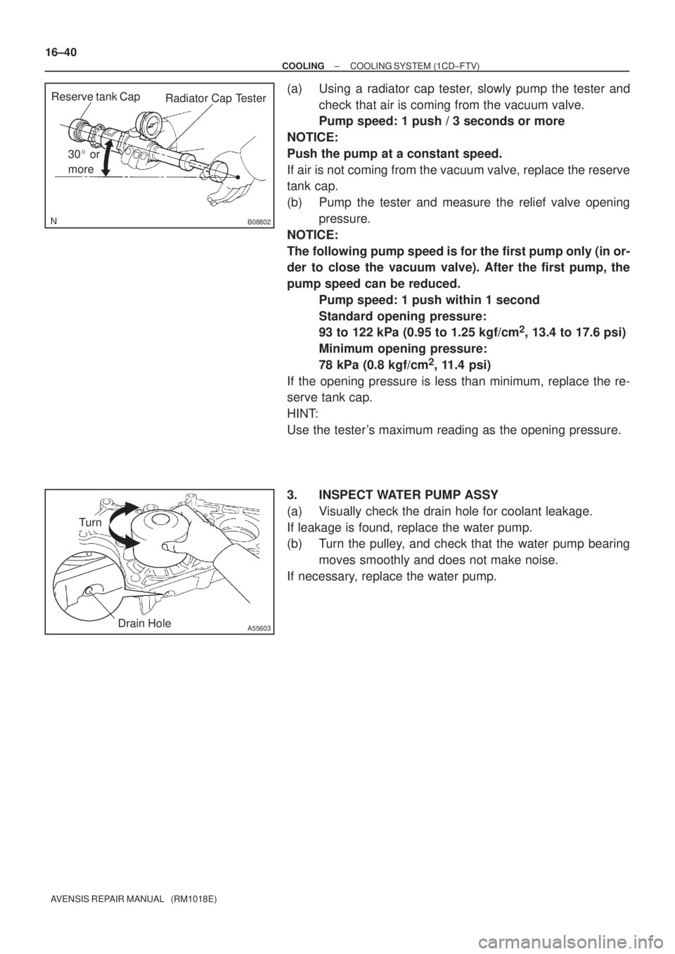
(a) Using a radiator cap tester, slowly pump the tester and
check that air is coming from the vacuum valve.
Pump speed: 1 push / 3 seconds or more
NOTICE:
Push the pump at a constant speed.
If air is not coming from the vacuum valve, replace the reserve
tank cap.
(b) Pump the tester and measure the relief valve opening
pressure.
NOTICE:
The following pump speed is for the first pump only (in or-
der to close the vacuum valve). After the first pump, the
pump speed can be reduced.
Pump speed: 1 push within 1 second
Standard opening pressure:
93 to 122 kPa (0.95 to 1.25 kgf/cm
2, 13.4 to 17.6 psi)
Minimum opening pressure:
78 kPa (0.8 kgf/cm
2, 11.4 psi)
If the opening pressure is less than minimum, replace the re-
serve tank cap.
HINT:
Use the tester's maximum reading as the opening pressure.
3. INSPECT WATER PUMP ASSY
(a) Visually check the drain hole for coolant leakage.
If leakage is found, replace the water pump.
(b) Turn the pulley, and check that the water pump bearing
moves smoothly and does not make noise.
If necessary, replace the water pump.
Page 161 of 1690
Radiator CapRadiator Cap Tester
30� or more
A51912
A79816Hole
Turn 16±4
± COOLINGCOOLING SYSTEM (1ZZ±FE/3ZZ±FE)
AVENSIS REPAIR MANUAL (RM1018E)
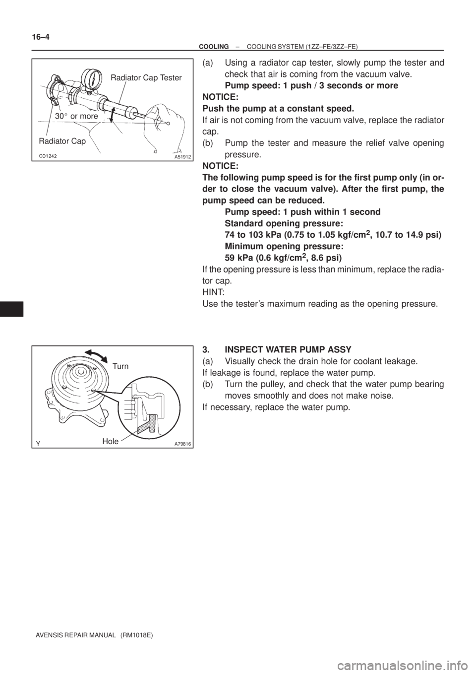
(a) Using a radiator cap tester, slowly pump the tester and
check that air is coming from the vacuum valve.
Pump speed: 1 push / 3 seconds or more
NOTICE:
Push the pump at a constant speed.
If air is not coming from the vacuum valve, replace the radiator
cap.
(b) Pump the tester and measure the relief valve opening
pressure.
NOTICE:
The following pump speed is for the first pump only (in or-
der to close the vacuum valve). After the first pump, the
pump speed can be reduced.
Pump speed: 1 push within 1 second
Standard opening pressure:
74 to 103 kPa (0.75 to 1.05 kgf/cm
2, 10.7 to 14.9 psi)
Minimum opening pressure:
59 kPa (0.6 kgf/cm
2, 8.6 psi)
If the opening pressure is less than minimum, replace the radia-
tor cap.
HINT:
Use the tester's maximum reading as the opening pressure.
3. INSPECT WATER PUMP ASSY
(a) Visually check the drain hole for coolant leakage.
If leakage is found, replace the water pump.
(b) Turn the pulley, and check that the water pump bearing
moves smoothly and does not make noise.
If necessary, replace the water pump.
Page 188 of 1690
3005C±02
±
DRIVE SHAFT / PROPELLER SHAFT DRIVE SHAFT, PROPELLER SHAFT, AXLE
30±1
AVENSIS REPAIR MANUAL (RM1018E)
DRIVE SHAFT, PROPELLER SHAFT, AXLE
PROBLEM SYMPTOMS TABLE
Use the table below to help you find the cause of the problem. The numbers \
indicate the priority of
the likely cause of the problem. Check each part in order. If necessary, replace these parts.
SymptomSuspect AreaSee page
Wander
5. Wheel
6. Front wheel alignment
7. Rear wheel alignment
8. Hub bearing (Worn)
9. Front shock absorber
10.Rear shock absorber28±1
26±6
27±4
30±2
26±10
27±8
Front wheel shimmy
1. Wheel (Imbalance)
2. Hub bearing (Worn)
3. Lower suspension arm ATM:
4. Lower suspension arm MTM:
5. Lower ball joint (Worm)
6. Front shock absorber28±1
30±2
26±16
26±21
26±24
26±10
Noise (Front)
1. Front drive shaft
2. Front shock absorber
3. Hub bearing (Worn)
4. Lower ball joint (Worm)30±6
26±10 30±2
26±24
Noise (Rear)1. Hub bearing (Worn)
2. Rear shock absorber30±2
27±8