Page 361 of 1690
90�
A09683
TDC Mark
Dot Mark
A09624
A09625
A09626
Alignment Mark
± ENGINE MECHANICALCAMSHAFT (1CD±FTV)
14±321
AVENSIS REPAIR MANUAL (RM1018E)
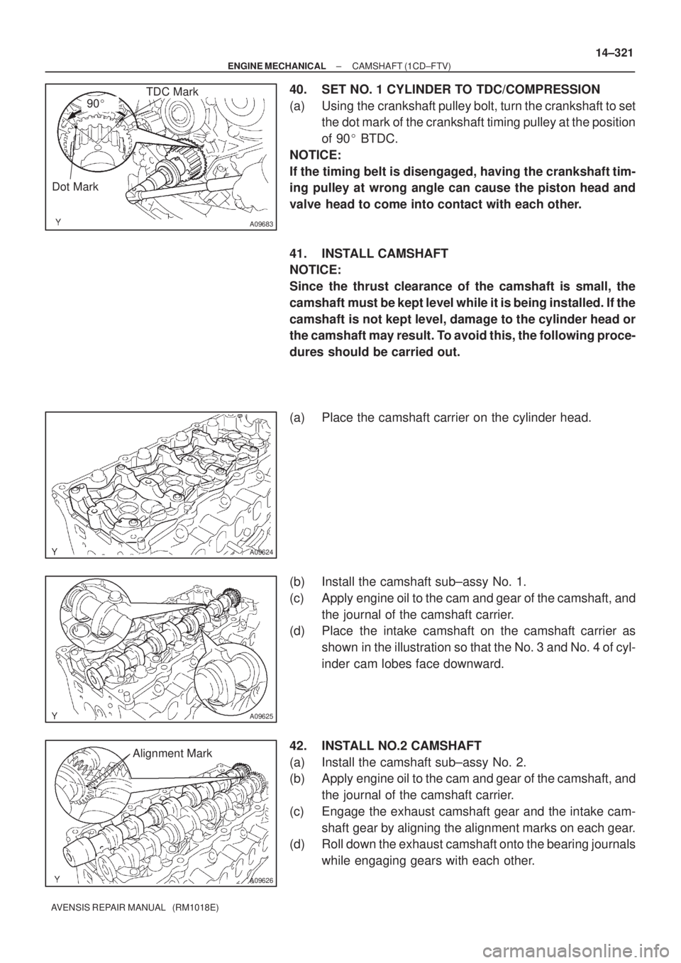
40. SET NO. 1 CYLINDER TO TDC/COMPRESSION
(a) Using the crankshaft pulley bolt, turn the crankshaft to set
the dot mark of the crankshaft timing pulley at the position
of 90� BTDC.
NOTICE:
If the timing belt is disengaged, having the crankshaft tim-
ing pulley at wrong angle can cause the piston head and
valve head to come into contact with each other.
41. INSTALL CAMSHAFT
NOTICE:
Since the thrust clearance of the camshaft is small, the
camshaft must be kept level while it is being installed. If the
camshaft is not kept level, damage to the cylinder head or
the camshaft may result. To avoid this, the following proce-
dures should be carried out.
(a) Place the camshaft carrier on the cylinder head.
(b) Install the camshaft sub±assy No. 1.
(c) Apply engine oil to the cam and gear of the camshaft, and
the journal of the camshaft carrier.
(d) Place the intake camshaft on the camshaft carrier as
shown in the illustration so that the No. 3 and No. 4 of cyl-
inder cam lobes face downward.
42. INSTALL NO.2 CAMSHAFT
(a) Install the camshaft sub±assy No. 2.
(b) Apply engine oil to the cam and gear of the camshaft, and
the journal of the camshaft carrier.
(c) Engage the exhaust camshaft gear and the intake cam-
shaft gear by aligning the alignment marks on each gear.
(d) Roll down the exhaust camshaft onto the bearing journals
while engaging gears with each other.
Page 372 of 1690
A62185
Mark
Mark
Mark
Timing Chain
Cover Surface
Timing
Notch
A11858
A62186
Paint Mark
A62178
Push 14±66
± ENGINE MECHANICALCAMSHAFT (1ZZ±FE/3ZZ±FE)
AVENSIS REPAIR MANUAL (RM1018E)
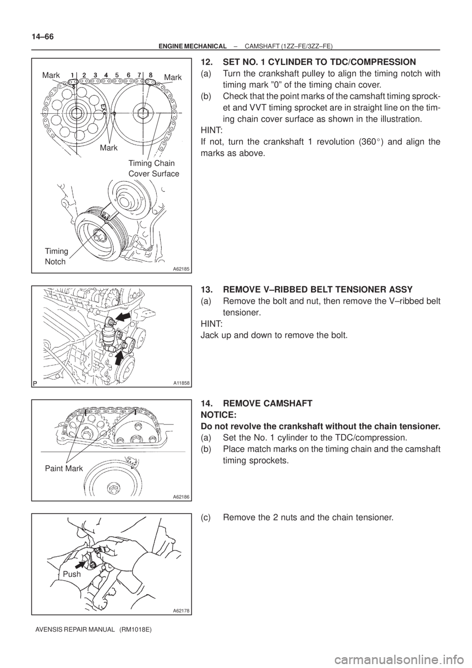
12. SET NO. 1 CYLINDER TO TDC/COMPRESSION
(a) Turn the crankshaft pulley to align the timing notch with
timing mark º0º of the timing chain cover.
(b) Check that the point marks of the camshaft timing sprock-
et and VVT timing sprocket are in straight line on the tim-
ing chain cover surface as shown in the illustration.
HINT:
If not, turn the crankshaft 1 revolution (360�) and align the
marks as above.
13. REMOVE V±RIBBED BELT TENSIONER ASSY
(a) Remove the bolt and nut, then remove the V±ribbed belt
tensioner.
HINT:
Jack up and down to remove the bolt.
14. REMOVE CAMSHAFT
NOTICE:
Do not revolve the crankshaft without the chain tensioner.
(a) Set the No. 1 cylinder to the TDC/compression.
(b) Place match marks on the timing chain and the camshaft
timing sprockets.
(c) Remove the 2 nuts and the chain tensioner.
Page 375 of 1690
A62192
Hold Pressure
DecompressAdvanced
Side Path Retard
Side Path
A62190
Advance
Side Path Retard Side
Path
Open
Close
Rubber Vinyl Tape Open Close
± ENGINE MECHANICALCAMSHAFT (1ZZ±FE/3ZZ±FE)
14±69
AVENSIS REPAIR MANUAL (RM1018E)
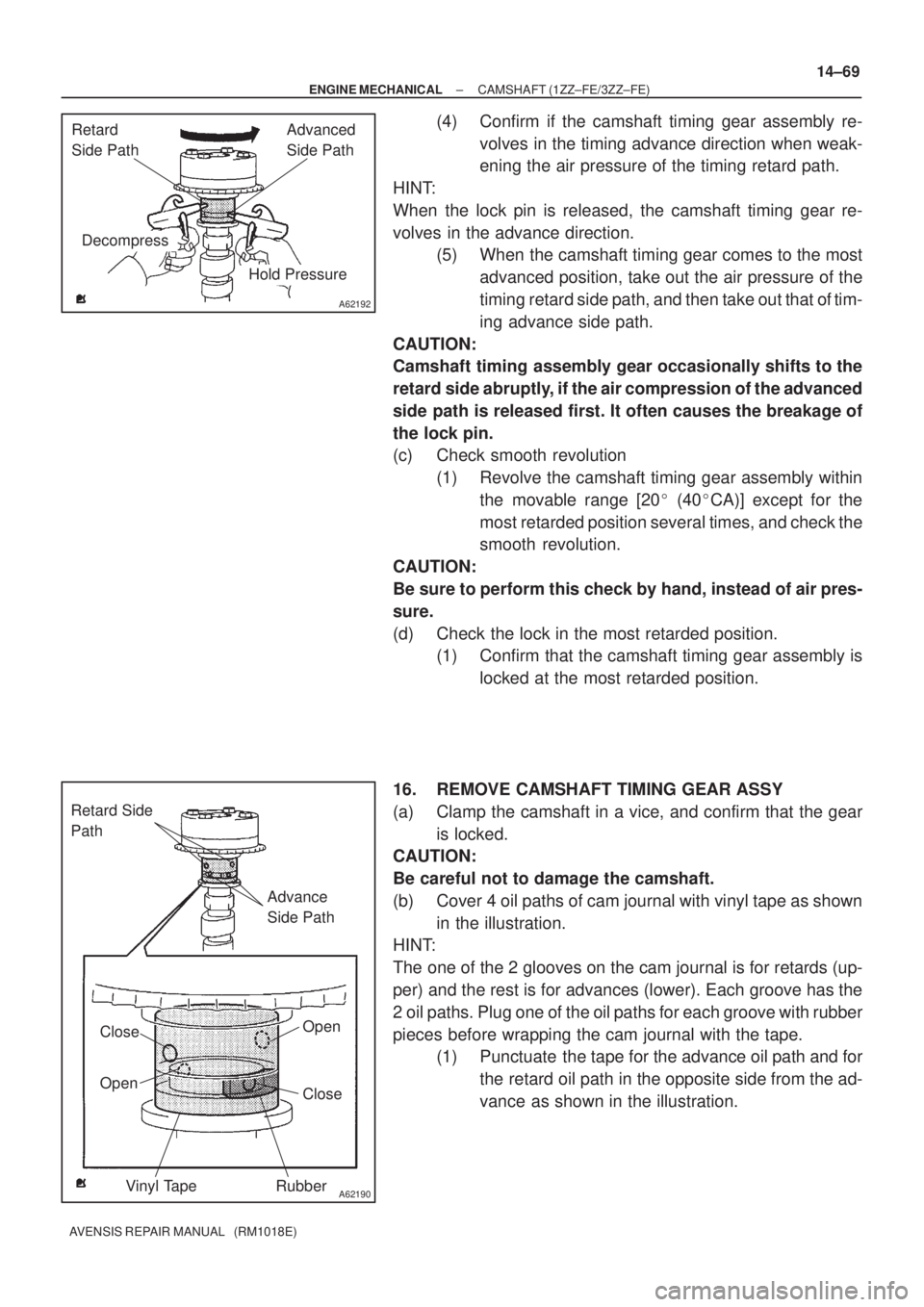
(4) Confirm if the camshaft timing gear assembly re-
volves in the timing advance direction when weak-
ening the air pressure of the timing retard path.
HINT:
When the lock pin is released, the camshaft timing gear re-
volves in the advance direction.
(5) When the camshaft timing gear comes to the most
advanced position, take out the air pressure of the
timing retard side path, and then take out that of tim-
ing advance side path.
CAUTION:
Camshaft timing assembly gear occasionally shifts to the
retard side abruptly, if the air compression of the advanced
side path is released first. It often causes the breakage of
the lock pin.
(c) Check smooth revolution
(1) Revolve the camshaft timing gear assembly within
the movable range [20� (40�CA)] except for the
most retarded position several times, and check the
smooth revolution.
CAUTION:
Be sure to perform this check by hand, instead of air pres-
sure.
(d) Check the lock in the most retarded position.
(1) Confirm that the camshaft timing gear assembly is
locked at the most retarded position.
16. REMOVE CAMSHAFT TIMING GEAR ASSY
(a) Clamp the camshaft in a vice, and confirm that the gear
is locked.
CAUTION:
Be careful not to damage the camshaft.
(b) Cover 4 oil paths of cam journal with vinyl tape as shown
in the illustration.
HINT:
The one of the 2 glooves on the cam journal is for retards (up-
per) and the rest is for advances (lower). Each groove has the
2 oil paths. Plug one of the oil paths for each groove with rubber
pieces before wrapping the cam journal with the tape.
(1) Punctuate the tape for the advance oil path and for
the retard oil path in the opposite side from the ad-
vance as shown in the illustration.
Page 376 of 1690
A62191
Advanced
Side Path Retard
Side Path
A62192
Hold Pressure
DecompressAdvanced
Side Path Retard
Side Path
A62193
Straight Pin Fringe Bolt
A62194
Straight Pin
Key Groove
14±70
± ENGINE MECHANICALCAMSHAFT (1ZZ±FE/3ZZ±FE)
AVENSIS REPAIR MANUAL (RM1018E)
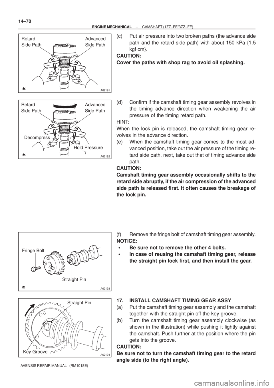
(c) Put air pressure into two broken paths (the advance side
path and the retard side path) with about 150 kPa {1.5
kgf�cm}.
CAUTION:
Cover the paths with shop rag to avoid oil splashing.
(d) Confirm if the camshaft timing gear assembly revolves in
the timing advance direction when weakening the air
pressure of the timing retard path.
HINT:
When the lock pin is released, the camshaft timing gear re-
volves in the advance direction.
(e) When the camshaft timing gear comes to the most ad-
vanced position, take out the air pressure of the timing re-
tard side path, next, take out that of timing advance side
path.
CAUTION:
Camshaft timing gear assembly occasionally shifts to the
retard side abruptly, if the air compression of the advanced
side path is released first. It often causes the breakage of
the lock pin.
(f) Remove the fringe bolt of camshaft timing gear assembly.
NOTICE:
�Be sure not to remove the other 4 bolts.
�In case of reusing the camshaft timing gear, release
the straight pin lock first, and then install the gear.
17. INSTALL CAMSHAFT TIMING GEAR ASSY
(a) Put the camshaft timing gear assembly and the camshaft
together with the straight pin off the key groove.
(b) Turn the camshaft timing gear assembly clockwise (as
shown in the illustration) while pushing it lightly against
the camshaft. Push further at the position where the pin
gets into the groove.
CAUTION:
Be sure not to turn the camshaft timing gear to the retard
angle side (to the right angle).
Page 388 of 1690
A77283
A77284
A77285
Unleaded Gasoline
Timing
Marks
�eaded Gasoline
Timing
Marks
Timing
Marks
Timing
Marks
± ENGINE MECHANICALCHAIN SUB±ASSY (1AZ±FE)
14±141
AVENSIS REPAIR MANUAL (RM1018E)
19. REMOVE ENGINE SERVICE COVER BRACKET RH (RHD(W/ AIR CONDITIONER) STEERING
POSITION TYPE)
(a) Remove the bolt and the engine service cover bracket RH.
20. REMOVE IGNITION COIL ASSY
(a) Remove the 4 bolts and 4 ignition coils.
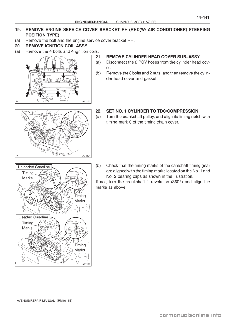
21. REMOVE CYLINDER HEAD COVER SUB±ASSY
(a) Disconnect the 2 PCV hoses from the cylinder head cov-
er.
(b) Remove the 8 bolts and 2 nuts, and then remove the cylin-
der head cover and gasket.
22. SET NO. 1 CYLINDER TO TDC/COMPRESSION
(a) Turn the crankshaft pulley, and align its timing notch with
timing mark 0 of the timing chain cover.
(b) Check that the timing marks of the camshaft timing gear
are aligned with the timing marks located on the No. 1 and
No. 2 bearing caps as shown in the illustration.
If not, turn the crankshaft 1 revolution (360�) and align the
marks as above.
Page 394 of 1690
A77285
Unleaded Gasoline
Timing
Marks
Leaded Gasoline
Timing
Marks
Timing
Marks
Timing
Marks
A52505
A77388
SST
± ENGINE MECHANICALCHAIN SUB±ASSY (1AZ±FE)
14±147
AVENSIS REPAIR MANUAL (RM1018E)
39. INSTALL CRANKSHAFT TIMING GEAR OR SPROCKET
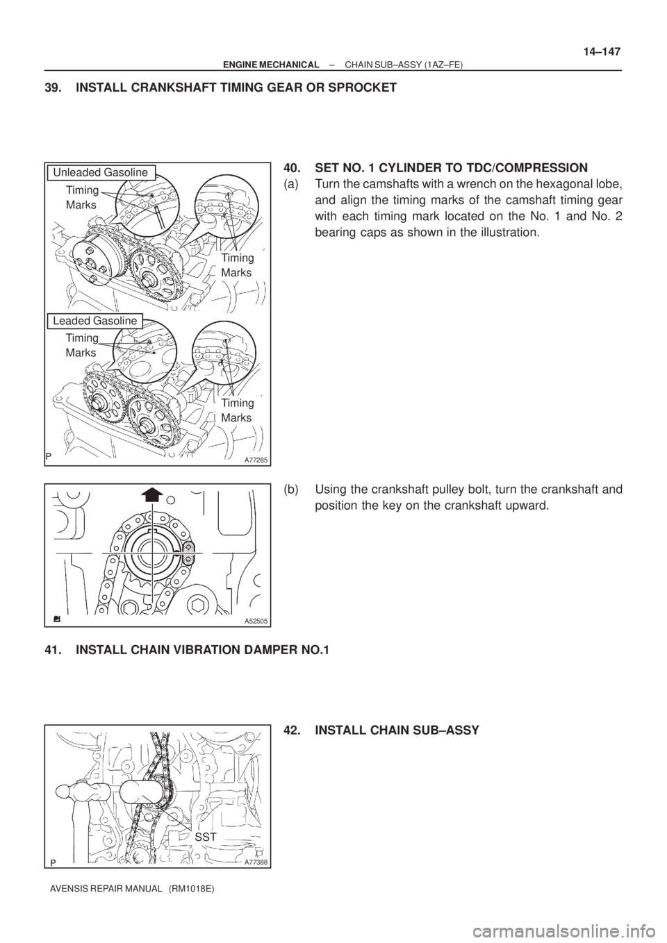
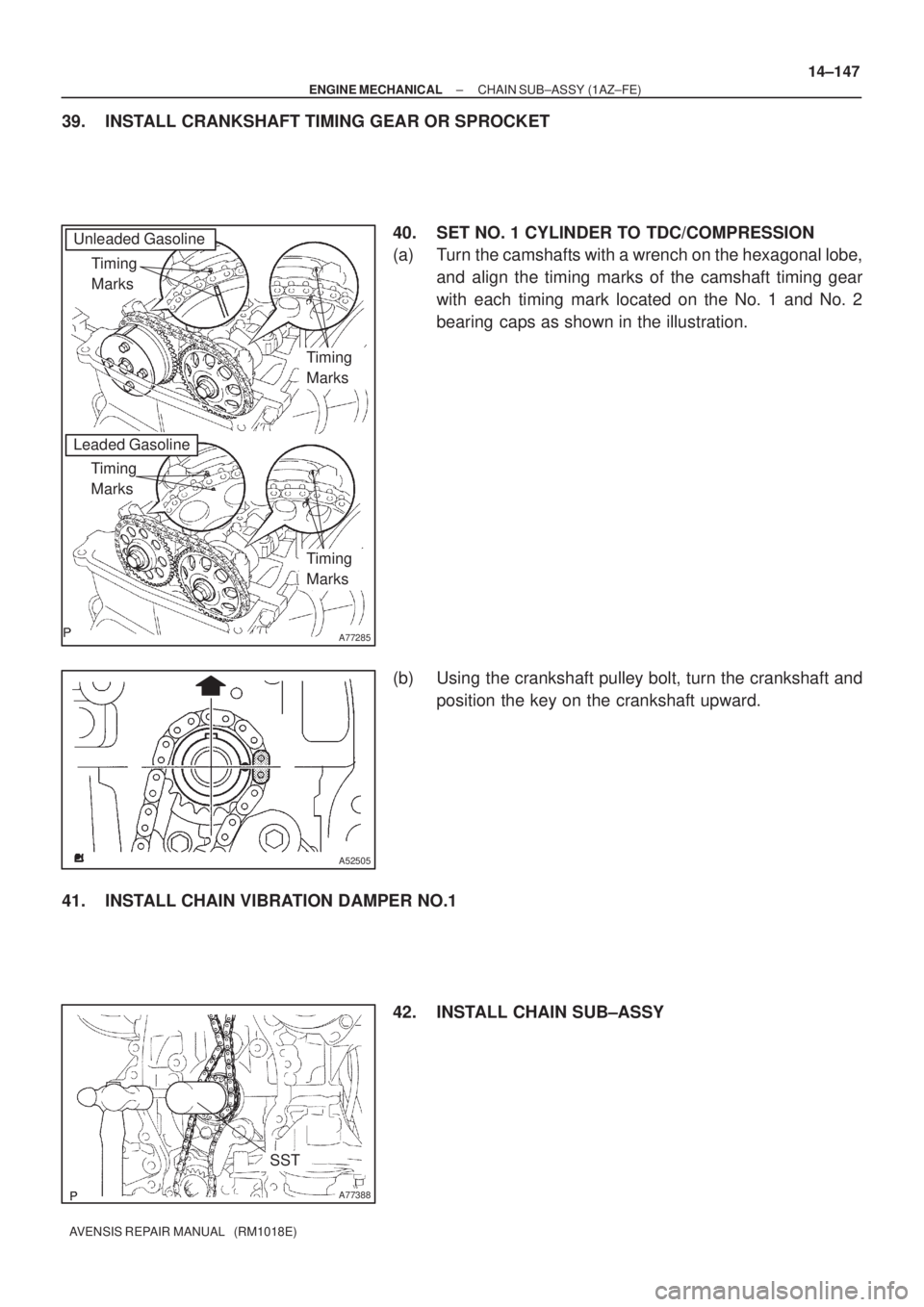
40. SET NO. 1 CYLINDER TO TDC/COMPRESSION
(a) Turn the camshafts with a wrench on the hexagonal lobe,
and align the timing marks of the camshaft timing gear
with each timing mark located on the No. 1 and No. 2
bearing caps as shown in the illustration.
(b) Using the crankshaft pulley bolt, turn the crankshaft and
position the key on the crankshaft upward.
41. INSTALL CHAIN VIBRATION DAMPER NO.1
42. INSTALL CHAIN SUB±ASSY
Page 402 of 1690
A77283
A77284
A77285
Unleaded Gasoline
Timing
Marks
�eaded Gasoline
Timing
Marks
Timing
Marks
Timing
Marks
± ENGINE MECHANICALCHAIN SUB±ASSY (1AZ±FE)
14±141
AVENSIS REPAIR MANUAL (RM1018E)
19. REMOVE ENGINE SERVICE COVER BRACKET RH (RHD(W/ AIR CONDITIONER) STEERING
POSITION TYPE)
(a) Remove the bolt and the engine service cover bracket RH.
20. REMOVE IGNITION COIL ASSY
(a) Remove the 4 bolts and 4 ignition coils.
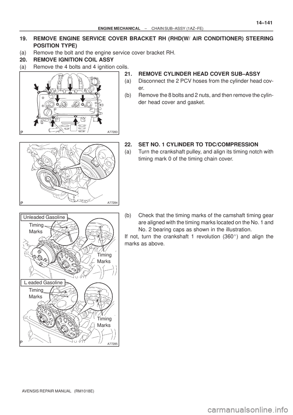
21. REMOVE CYLINDER HEAD COVER SUB±ASSY
(a) Disconnect the 2 PCV hoses from the cylinder head cov-
er.
(b) Remove the 8 bolts and 2 nuts, and then remove the cylin-
der head cover and gasket.
22. SET NO. 1 CYLINDER TO TDC/COMPRESSION
(a) Turn the crankshaft pulley, and align its timing notch with
timing mark 0 of the timing chain cover.
(b) Check that the timing marks of the camshaft timing gear
are aligned with the timing marks located on the No. 1 and
No. 2 bearing caps as shown in the illustration.
If not, turn the crankshaft 1 revolution (360�) and align the
marks as above.
Page 408 of 1690
A77285
Unleaded Gasoline
Timing
Marks
Leaded Gasoline
Timing
Marks
Timing
Marks
Timing
Marks
A52505
A77388
SST
± ENGINE MECHANICALCHAIN SUB±ASSY (1AZ±FE)
14±147
AVENSIS REPAIR MANUAL (RM1018E)
39. INSTALL CRANKSHAFT TIMING GEAR OR SPROCKET
40. SET NO. 1 CYLINDER TO TDC/COMPRESSION
(a) Turn the camshafts with a wrench on the hexagonal lobe,
and align the timing marks of the camshaft timing gear
with each timing mark located on the No. 1 and No. 2
bearing caps as shown in the illustration.
(b) Using the crankshaft pulley bolt, turn the crankshaft and
position the key on the crankshaft upward.
41. INSTALL CHAIN VIBRATION DAMPER NO.1
42. INSTALL CHAIN SUB±ASSY