Page 33 of 1690

67±33
A")
670SL±01
BE4029
Tester Probe
Tin FoilHeat Wire
E32576
BE0150
Repair Point
Masking TapeBroken
Wire
BE0151
Repair PointFine Tip Brush
Glass
± AUDIO & VISUAL SYSTEMWINDOW GLASS (ANTENNA WIRE)
67±33
AVENSIS REPAIR MANUAL (RM1018E)
WINDOW GLASS (ANTENNA WIRE)
REPAIR
1. INSPECT WINDOW GLASS (ANTENNA WIRE)
NOTICE:
When cleaning the glass, wipe it in the direction of the wire
with a soft and dry cloth. Take care not to damage the wire.
Do not use detergents or glass cleaners with abrasive in-
gredients. When measuring voltage, wind a piece of tin foil
around the tip of the tester probe and press the foil against
the wire with your finger, as shown in the illustration.
(a) Check the continuity, at the center of each antenna wire,
as shown in the illustration.
2. REPAIR WINDOW GLASS (ANTENNA WIRE)
(a) Clean the broken wire tips with a grease, wax and silicone
remover.
(b) Place the masking tape along both sides of the wire to be
repaired.
(c) Thoroughly mix the repair agent (Dupont paste No.4817).
(d) Using a fine tip brush, apply a small amount of the mixture
to the wire.
(e) After a few minutes, remove the masking tape.
(f) Do not repair the defogger wire for at least 24 hours after-
wards.
Page 43 of 1690
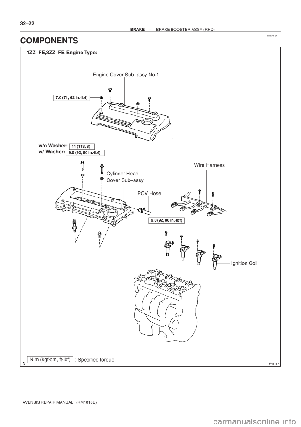
320W3±01
F45167
Engine Cover Sub±assy No.1
1ZZ±FE,3ZZ±FE Engine Type:
Wire Harness
Ignition Coil Cylinder Head
Cover Sub±assy
7.0 (71, 62 in.�lbf)
PCV Hose
N�m (kgf�cm, ft�lbf)
: Specified torquex8 w/o Washer:
w/ Washer:
11 (113, 8)
9.0 (92, 80 in.�lbf)
9.0 (92, 80 in.�lbf)
32±22
± BRAKEBRAKE BOOSTER ASSY (RHD)
AVENSIS REPAIR MANUAL (RM1018E)
COMPONENTS
Page 46 of 1690

32±25
AVENSIS REPAIR MANUAL (RM1018E)
REPLACEMENT
NOTICE:
Do not adjust the brake booster push rod.
1. DRAIN BRAKE FLUID
NOTICE:
Wash the b")
320W4±01
G24211
F42291
±
BRAKE BRAKE BOOSTER ASSY (RHD)
32±25
AVENSIS REPAIR MANUAL (RM1018E)
REPLACEMENT
NOTICE:
Do not adjust the brake booster push rod.
1. DRAIN BRAKE FLUID
NOTICE:
Wash the brake fluid off immediately if it adheres to any painted surface\
.
2.REMOVE BRAKE MASTER CYLINDER SUB±ASSY (See page 32±13)
(a) w/o VSC:
SST 09023±00100
(b) w/ VSC: SST 09023±38400
3.REMOVE CLUTCH MASTER CYLINDER ASSY (M/T TRANSAXLE) (See page 42±13) SST 09023±00100
4. REMOVE ENGINE ASSEMBLY WITH TRANSAXLE (1AZ±FSE ENGINE TYPE) (See page 14±204)
5. REMOVE ENGINE COVER NO.1
6.REMOVE IGNITION COIL ASSY (GASOLINE ENGINE TYPE) (See page 14±81)
7.REMOVE CYLINDER HEAD COVER SUB±ASSY (GASOLINE ENGINE TYPE) (See page 14±81)
8.REMOVE TIMING BELT NO.2 COVER (DIESEL ENGINE TYPE) (See page 14±307)
9.REMOVE CYLINDER HEAD COVER SUB±ASSY (DIESEL ENGINE TYPE) (See page 14±318)
10.REMOVE INJECTOR ASSY (DIESEL ENGINE TYPE) (See page 14±318)
11. REMOVE FRONT WHEEL RH
12. REMOVE BRAKE TUBE
(a) w/o VSC:Using SST, disconnect the 6 brake tubes from the brake
actuator.
SST 09023±00100
(b) w/ VSC: Using SST, disconnect the 6 brake tubes from the brake
actuator.
SST 09023±00100, 09023±38400
Page 52 of 1690

F45057
w/o VSC:
w/ VSC:
To Master
Cylinder Rear
To
Master
Cylinder
Front
To Rear Wheel
RH
To Front Wheel LH
To Front Wheel RH
To Rear Wheel
LH
A
To
Master
Cylinder
FrontTo Master
Cylinder
Rear
To Rear
Wheel RH
To Front Wheel LHTo Front Wheel RH
To Rear
Wheel LH
AA
AA
BB
C80806
±
BRAKE BRAKE BOOSTER ASSY (RHD)
32±31
AVENSIS REPAIR MANUAL (RM1018E)
(e) w/o VSC:
Using SST, connect the 6 brake tubes to the brake actua-
tor, as shown in the illustration.
SST 09023±00100
Torque: 15 N �m (155 kgf �cm, 11 ft �lbf)
(f) w/ VSC: Using SST, connect the 6 brake tubes to the brake actua-
tor as shown in the illustration.
SST 09023±00100, 09023±38400
Torque:
A: 15 N �m (155 kgf �cm, 11 ft �lbf)
B: 29 N �m (296 kgf �cm, 21 ft �lbf)
(g) Install the brake tube clamps with the 2 bolts. Torque: 5.4 N �m (55 kgf �cm, 48 in. �lbf)
20. INSTALL FRONT WHEEL RH
21.INSTALL CYLINDER HEAD COVER SUB±ASSY (GASOLINE ENGINE TYPE) (See page 14±81)
22.INSTALL IGNITION COIL ASSY (GASOLINE ENGINE TYPE) (See page 14±81)
23.INSTALL INJECTOR ASSY (DIESEL ENGINE TYPE) (See page 14±318)
24.INSTALL CYLINDER HEAD COVER SUB±ASSY (DIESEL ENGINE TYPE) (See page 14±318)
25.INSTALL TIMING BELT NO.2 COVER (DIESEL ENGINE TYPE) (See page 14±307)
Page 68 of 1690

PROBLEM SYMPTOMS TABLE
Use the table below to help you find the cause of the problem. The numbers \
indicate the probability of")
3201B±12
32±2
±
BRAKE BRAKE SYSTEM
AVENSIS REPAIR MANUAL (RM1018E)
PROBLEM SYMPTOMS TABLE
Use the table below to help you find the cause of the problem. The numbers \
indicate the probability of the
problems in descending order. Check each part in order. If necessary, replace these parts.
SymptomSuspect AreaSee page
Low pedal or spongy pedal
3. Fluid leaks in brake system
4. Air in brake system
5. Piston seals (Worn or damaged)
6. Brake master cylinder (faulty)
7. Brake booster push rod (Out of adjustment) ±
32±4
32±41
32±47
32±13
32±13
Brake drag
1. Brake pedal free play (Minimal)
2. Parking brake lever travel (Out of adjustment)
3. Parking brake wire (Sticking)
4. Disk brake pad (Cracked or distorted)
5. Piston (Stuck or Frozen)
6. Brake booster push rod (Out adjustment)
7. Vacuum leaks in brake booster system
8. Brake master cylinder (Faulty)32±6
33±2
33±2
32±41
32±47
32±41
32±47
32±13
32±17
32±21
32±13
Brake pull
1. Piston (Stuck or Frozen)
2. Pad or lining (Oily)
3. Disc (Scored)
4. Pad (Cracked or distorted) 32±41
32±47
32±41
32±47
32±41
32±47
32±41
32±47
Hard pedal but brake inefficient
1. Fluid leaks in brake system
2. Air in brake system
3. Pad (Worn)
4. Pad (Cracked or distorted)
5. Pad (Oily)
6. Pad (Glazed)
7. Disc (Scored)
8. Booster push rod (Out of adjustment)
9. Vacuum leaks for booster system ±
32±4
32±41
32±47
32±41
32±47
32±41
32±47
32±41
32±47
32±41
32±47
32±13
32±17
32±21
Page 75 of 1690

24. INSTALL FRONT DISC BRAKE CYLINDER SLIDE PIN
KIT
(a) Apply")
F45419
Cylinder Slide Pin
Lithium soap base glycol grease
F45421
Union Bolt
±
BRAKE FRONT BRAKE
32±45
AVENSIS REPAIR MANUAL (RM1018E)
24. INSTALL FRONT DISC BRAKE CYLINDER SLIDE PIN
KIT
(a) Apply lithium soap base glycol grease to the a new front
disc brake cylinder slide bush.
(b) Install the front disc brake cylinder slide bush to the bot- tom side of the front disc brake cylinder slide pin (No.2).
(c) Apply lithium soap base glycol grease to the sliding part
and the sealing surface of the 2 cylinder slide pins.
(d) Install the 2 front disc brake cylinder slide pins to the front disc brake cylinder mounting LH.
25. INSTALL FRONT DISC BRAKE PAD KIT
(a) Install the 2 front disc brake pad support plates (No.1) and 2 front disc bra\
ke pad support plates (No.2) to the front disc brake cylinder mounting LH.
(b) Install the disc brake pad kit front to the front disc brake cylinder mo\
unting LH.
NOTICE:
There should be no oil or grease on the friction surfaces of the pads an\
d the disc.
26. INSTALL DISC BRAKE CYLINDER ASSY LH
(a) Install the disc brake cylinder assy LH with the 2 bolts.Torque: 30 N �m (306 kgf �cm, 22 ft �lbf)
(b) Install a new gasket and flexible hose with the union bolt.
Torque: 29 N �m (296 kgf �cm, 21 ft �lbf)
HINT:
Install the flexible hose lock securely in the lock hole in the disc
brake cylinder assy LH.
27.FILL RESERVOIR WITH BRAKE FLUID (See page 32±4)
28.BLEED MASTER CYLINDER (See page 32±4)
(a) w/o VSC: SST 09023±00100
(b) w/ VSC: SST 09023±38400
29.BLEED BRAKE LINE (See page 32±4)
30.CHECK FLUID LEVEL IN RESERVOIR (See page 32±4)
31. CHECK BRAKE FLUID LEAKAGE
32. INSTALL FRONT WHEEL
Torque: 103 N �m (1,050 kgf �cm, 76 ft �lbf)
Page 87 of 1690

STEERING SENSOR
REPLACEMENT
1.PRECAUTION (See page 60±1)
2. REMOVE PLACE FRONT WHEELS FACING STRAIGHT")
320G5±02
F45426
F45427
F42642
±
BRAKE STEERING SENSOR
32±65
AVENSIS REPAIR MANUAL (RM1018E)
STEERING SENSOR
REPLACEMENT
1.PRECAUTION (See page 60±1)
2. REMOVE PLACE FRONT WHEELS FACING STRAIGHT AHEAD
3.DISCONNECT BATTERY NEGATIVE TERMINAL (See page 60±1)
4.REMOVE HORN BUTTON ASSY (See page 60±17)
5.REMOVE STEERING WHEEL ASSY (See page 50±9)
6.REMOVE STEERING COLUMN COVER LWR (See page 50±9)
7. REMOVE STEERING COLUMN COVER W/INSTRUMENT CLUSTER FINISH PANEL ASSY
(See page 50±9)
8.REMOVE STEERING COLUMN ASSY(See page 50±9)
9.REMOVE STEERING INTERMEDIATE SHAFT ASSY NO.2 (See page 50±9)
10. REMOVE STEERING SENSOR
(a) Place the steering column assy on the V±blocks and rub-ber stick.
(b) Using a extension bar and hammer, remove the steering column bracket spacer and 2 tilt steering support collar
No.1 from the steering column assy.
NOTICE:
�During this procedure, do not apply the strong shock
to the steering sensor.
�Do not apply any oil or grease on the pin.
(c) Using a screwdriver, remove the bush from the steering column assy.
(d) Disconnect the pick on the steering sensor and steering sensor adapter, then remove the steering sensor from the
column shaft.
(e) Remove the steering sensor adapter.
Page 88 of 1690

11. INSTALL STEERING SENSOR
(a) Install the steering sensor adapter to the column shaft.
HINT:
At that tim")
F42641
F42642
F45427
F45426
32±66
±
BRAKE STEERING SENSOR
AVENSIS REPAIR MANUAL (RM1018E)
11. INSTALL STEERING SENSOR
(a) Install the steering sensor adapter to the column shaft.
HINT:
At that time, the projection of the steering sensor adapter
should be fit in the hole on the steering column shaft.
(b) Install the steering sensor to the column shaft.
HINT:
�At that time, the pick of the steering sensor should be fit
to the pick of the steering sensor adapter.
�After installation, make sure the steering sensor is fixed
securely in the steering sensor adapter.
(c) Place the steering column assy on the V±blocks and rub- ber stick.
(d) Install the 2 new tilt steering support collar No.1 to the steering column assy.
(e) Using a extension bar and hammer, install the steering column bracket spacer to the steering column assy.
NOTICE:
�During this procedure, do not apply the strong shock
to the steering sensor.
�Do not apply any grease or oil on the pin.
12.INSTALL STEERING INTERMEDIATE SHAFT ASSY NO.2 (See page 50±9)
13.INSTALL STEERING COLUMN ASSY (See page 50±9)
14.INSTALL SPIRAL CABLE SUB±ASSY (See page 60±26)
15. INSTALL STEERING COLUMN COVER W/INSTRUMENT CLUSTER FINISH PANEL ASSY (See page 50±9)
16.INSTALL STEERING COLUMN COVER LWR (See page 50±9)
17.INSTALL STEERING WHEEL ASSY (See page 50±9)
18. INSPECT STEERING WHEEL CENTER POINT
19.INSTALL HORN BUTTON ASSY (See page 60±17)