Page 202 of 1690
30093±02
������F45576
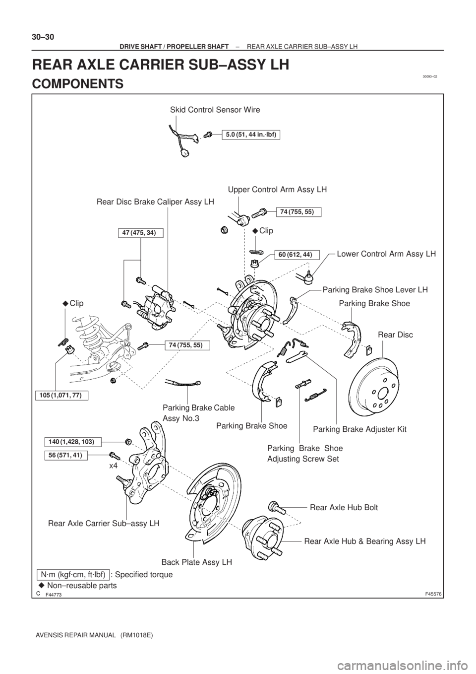
Skid Control Sensor Wire
5.0 (51, 44 in.�lbf)
Upper Control Arm Assy LH
�Clip
74 (755, 55)
60 (612, 44)Lower Control Arm Assy LH
Parking Brake Shoe
Rear Disc
47 (475, 34)
Rear Disc Brake Caliper Assy LH
�Clip
105 (1,071, 77)
Parking Brake Shoe
140 (1,428, 103)
56 (571, 41)
Rear Axle Carrier Sub±assy LH
Rear Axle Hub & Bearing Assy LH
Rear Axle Hub Bolt
x4
N�m (kgf�cm, ft�lbf) : Specified torque
� Non±reusable partsParking Brake Cable
Assy No.3
Parking Brake Shoe
Adjusting Screw Set
Parking Brake Adjuster Kit
Parking Brake Shoe Lever LH
74 (755, 55)
Back Plate Assy LH
30±30
± DRIVE SHAFT / PROPELLER SHAFTREAR AXLE CARRIER SUB±ASSY LH
AVENSIS REPAIR MANUAL (RM1018E)
REAR AXLE CARRIER SUB±ASSY LH
COMPONENTS
Page 204 of 1690
������F45753HoldTurn
SST
G21537
G21542
G20965
30±32
± DRIVE SHAFT / PROPELLER SHAFTREAR AXLE CARRIER SUB±ASSY LH
AVENSIS REPAIR MANUAL (RM1018E)
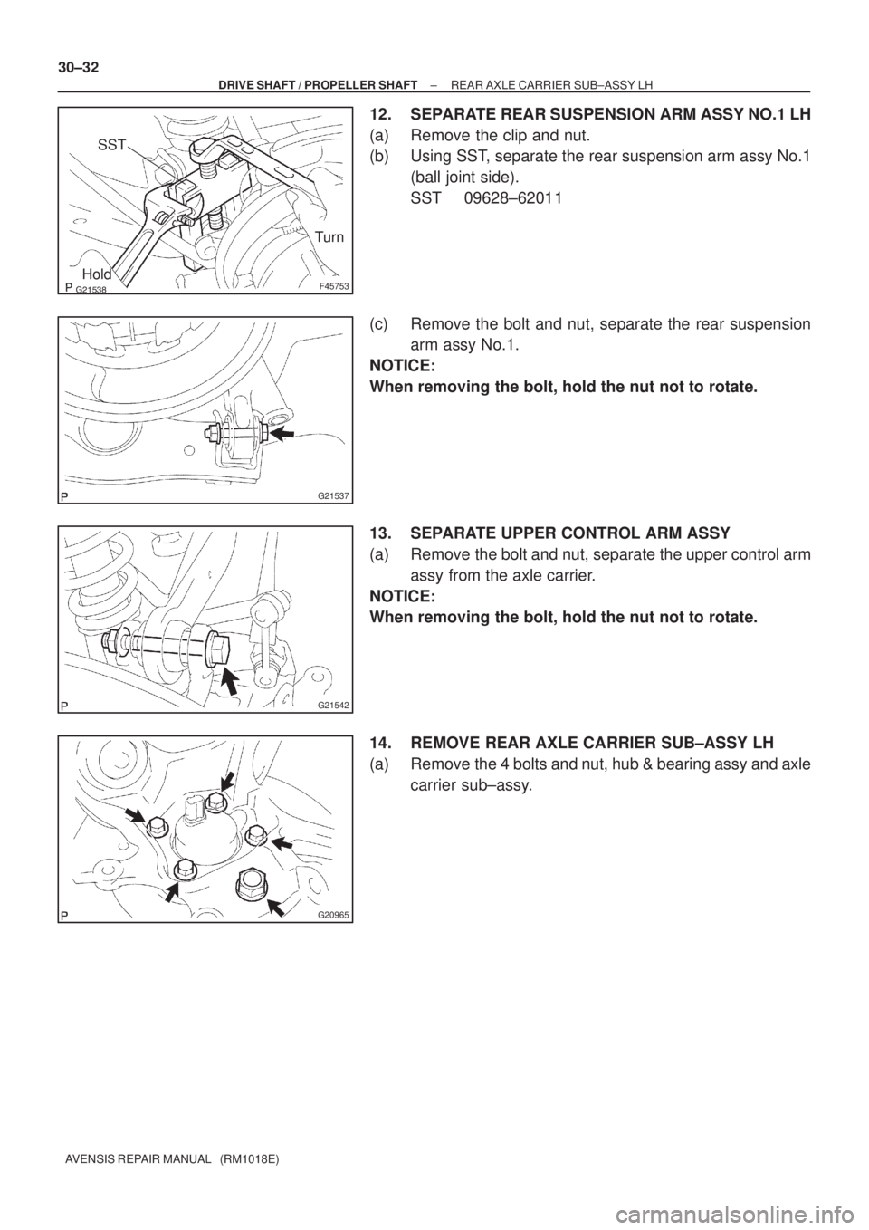
12. SEPARATE REAR SUSPENSION ARM ASSY NO.1 LH
(a) Remove the clip and nut.
(b) Using SST, separate the rear suspension arm assy No.1
(ball joint side).
SST 09628±62011
(c) Remove the bolt and nut, separate the rear suspension
arm assy No.1.
NOTICE:
When removing the bolt, hold the nut not to rotate.
13. SEPARATE UPPER CONTROL ARM ASSY
(a) Remove the bolt and nut, separate the upper control arm
assy from the axle carrier.
NOTICE:
When removing the bolt, hold the nut not to rotate.
14. REMOVE REAR AXLE CARRIER SUB±ASSY LH
(a) Remove the 4 bolts and nut, hub & bearing assy and axle
carrier sub±assy.
Page 205 of 1690
G21613
G20965
G21542
G21537
± DRIVE SHAFT / PROPELLER SHAFTREAR AXLE CARRIER SUB±ASSY LH
30±33
AVENSIS REPAIR MANUAL (RM1018E)
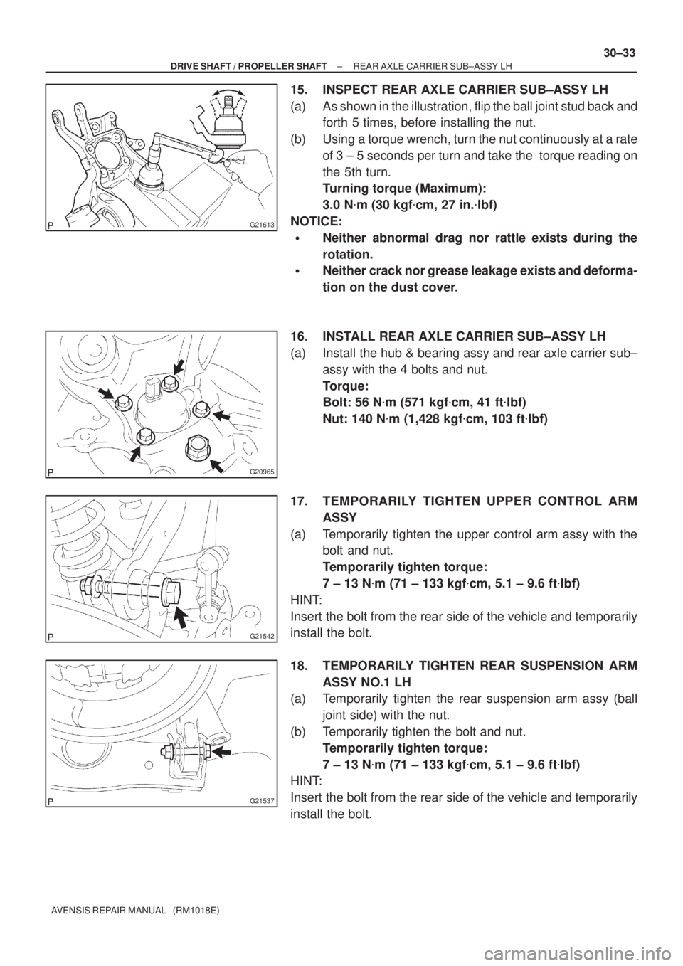
15. INSPECT REAR AXLE CARRIER SUB±ASSY LH
(a) As shown in the illustration, flip the ball joint stud back and
forth 5 times, before installing the nut.
(b) Using a torque wrench, turn the nut continuously at a rate
of 3 ± 5 seconds per turn and take the torque reading on
the 5th turn.
Turning torque (Maximum):
3.0 N�m (30 kgf�cm, 27 in.�lbf)
NOTICE:
�Neither abnormal drag nor rattle exists during the
rotation.
�Neither crack nor grease leakage exists and deforma-
tion on the dust cover.
16. INSTALL REAR AXLE CARRIER SUB±ASSY LH
(a) Install the hub & bearing assy and rear axle carrier sub±
assy with the 4 bolts and nut.
Torque:
Bolt: 56 N�m (571 kgf�cm, 41 ft�lbf)
Nut: 140 N�m (1,428 kgf�cm, 103 ft�lbf)
17. TEMPORARILY TIGHTEN UPPER CONTROL ARM
ASSY
(a) Temporarily tighten the upper control arm assy with the
bolt and nut.
Temporarily tighten torque:
7 ± 13 N�m (71 ± 133 kgf�cm, 5.1 ± 9.6 ft�lbf)
HINT:
Insert the bolt from the rear side of the vehicle and temporarily
install the bolt.
18. TEMPORARILY TIGHTEN REAR SUSPENSION ARM
ASSY NO.1 LH
(a) Temporarily tighten the rear suspension arm assy (ball
joint side) with the nut.
(b) Temporarily tighten the bolt and nut.
Temporarily tighten torque:
7 ± 13 N�m (71 ± 133 kgf�cm, 5.1 ± 9.6 ft�lbf)
HINT:
Insert the bolt from the rear side of the vehicle and temporarily
install the bolt.
Page 207 of 1690
±
DRIVE SHAFT / PROPELLER SHAFT REAR AXLE CARRIER SUB±ASSY LH
30±35
AVENSIS REPAIR MANUAL (RM1018E)
34. FULLY TIGHTEN UPPER CONTROL ARM ASSY
(a) Fully tighten the bolt.
Torque: 74 N �m (755 kgf �cm, 55 ft �lbf)
NOTICE:
When installing the bolt, hold the nut not to rotate.
35. FULLY TIGHTEN REAR SUSPENSION ARM ASSY NO.1 LH
(a) Fully tighten the nut (ball joint side). Torque: 105 N �m (1,071 kgf �cm, 77 ft �lbf)
(b) Install the clip.
NOTICE:
If the holes for the clip are not aligned, tighten the nut up to 60 � further.
(c) Fully tighten the bolt and nut.
Torque: 74 N �m (755 kgf �cm, 55 ft �lbf)
NOTICE:
When installing the bolt, hold the nut not to rotate.
36. FULLY TIGHTEN LOWER CONTROL ARM ASSY LH
(a) Fully tighten the nut. Torque: 60 N �m (612 kgf �cm, 44 ft �lbf)
(b) Install the clip.
NOTICE:
If the holes for the clip are not aligned, tighten the nut up to 60 � further.
(c) Fully tighten the bolt (member side). Torque: 105 N �m (1,071 kgf �cm, 77 ft �lbf)
NOTICE:
When installing the bolt, hold the nut not to rotate.
37.INSPECT AND ADJUST PARKING BRAKE LEVER TRAVEL (See page 33±2)
38.INSPECT AND ADJUST REAR WHEEL ALIGNMENT (See page 27±4)
39. CHECK ABS SPEED SENSOR SIGNAL
(a)ABD WITH EBD SYSTEM (See page 05±699)
(b)ABD WITH EBD & BA & TRC & VSC SYSTEM ( See page 05±756)
Page 1253 of 1690
270E0±01
������G26285
w/ Height Control Sensor:
5.8 (59, 51 in.�lbf)
80 (816, 59)
Rear Suspension Member Sub±assy
Rear Shock Absorber
Cushion Washer No.1
Coil Rear Spring
Rear Coil Spring Insulator Upper LH
Rear Spring Bumper No.1 LH
Rear Suspension Support Assy LH
Rear Spring Front Bracket
Sub±assy LH
Rear Shock
Absorber Cushion No.1
Lower Control Arm Assy RH
Rear Shock Absorber
Assy LH
160 (1,632, 118)
110 (1,122, 81)
65 (663, 48)
Rear Suspension
Support Stopper
Rear Suspension Arm
Bracket Assy LH
Rear Suspension
Arm Bush No.1�Camber Adjust Cam Assy
Rear Suspension Arm Assy No.1 LH
74 (755, 55)
105 (1,071, 77)
44 (449, 32)
74 (755, 55)
74 (755, 55)
Parking Brake Cable Assy No.3
5.0 (51, 44 in.�lbf)Rear Axle Carrier Sub±assy LH
Skid Control Sensor Wire
74 (755, 55)
Upper Control Arm Assy
Camber Adjust Cam No.2
Lower Control Arm Assy LH
105 (1,071, 77)
5.0 (51, 44 in.�lbf)
60 (612, 44)
N�m (kgf�cm, ft�lbf) : Specified torque
Non±reusable part �
56 (571, 41)
�56 (571, 41)
Clip
Clip 27±2
± REAR SUSPENSIONREAR SUSPENSION
AVENSIS REPAIR MANUAL (RM1018E)
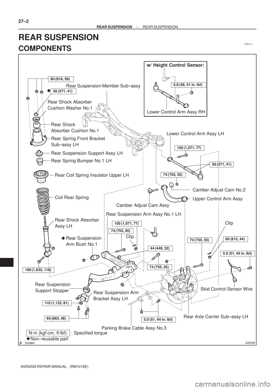
REAR SUSPENSION
COMPONENTS
Page 1256 of 1690
G23871
G23872
G23873
SST
G23880
������G23883
SST 27±16
± REAR SUSPENSIONREAR SUSPENSION ARM ASSY NO.1 LH
AVENSIS REPAIR MANUAL (RM1018E)
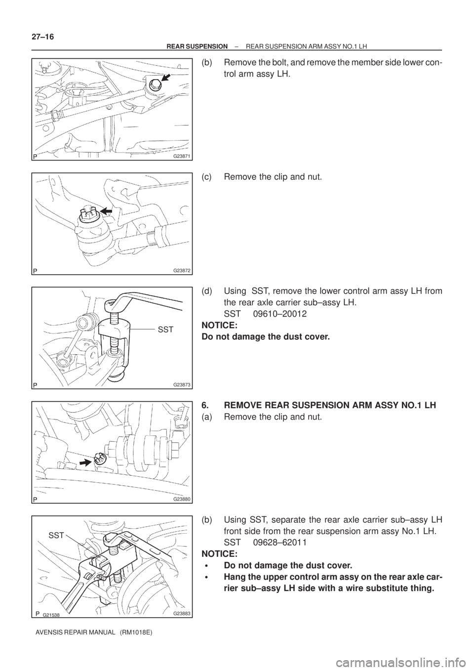
(b) Remove the bolt, and remove the member side lower con-
trol arm assy LH.
(c) Remove the clip and nut.
(d) Using SST, remove the lower control arm assy LH from
the rear axle carrier sub±assy LH.
SST 09610±20012
NOTICE:
Do not damage the dust cover.
6. REMOVE REAR SUSPENSION ARM ASSY NO.1 LH
(a) Remove the clip and nut.
(b) Using SST, separate the rear axle carrier sub±assy LH
front side from the rear suspension arm assy No.1 LH.
SST 09628±62011
NOTICE:
�Do not damage the dust cover.
�Hang the upper control arm assy on the rear axle car-
rier sub±assy LH side with a wire substitute thing.
Page 1271 of 1690
270E5±01
G25775
G21542
G23879
Matchmarks
G23879
Matchmarks
±
REAR SUSPENSION UPPER CONTROL ARM ASSY
27±27
AVENSIS REPAIR MANUAL (RM1018E)
UPPER CONTROL ARM ASSY
REPLACEMENT
HINT:
COMPONENTS: See page 27±2.
1. REMOVE REAR WHEEL
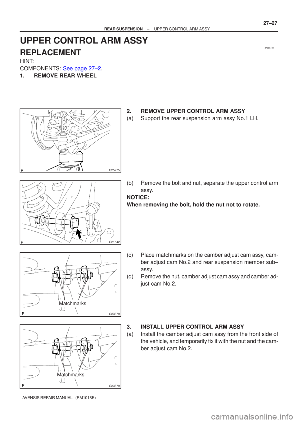
2. REMOVE UPPER CONTROL ARM ASSY
(a) Support the rear suspension arm assy No.1 LH.
(b) Remove the bolt and nut, separate the upper control armassy.
NOTICE:
When removing the bolt, hold the nut not to rotate.
(c) Place matchmarks on the camber adjust cam assy, cam- ber adjust cam No.2 and rear suspension member sub±
assy.
(d) Remove the nut, camber adjust cam assy and camber ad-
just cam No.2.
3. INSTALL UPPER CONTROL ARM ASSY
(a) Install the camber adjust cam assy from the front side of the vehicle, and temporarily fix it with the nut and the cam-
ber adjust cam No.2.
Page 1272 of 1690
G21542
G21542
G23879
Matchmarks
27±28
±
REAR SUSPENSION UPPER CONTROL ARM ASSY
AVENSIS REPAIR MANUAL (RM1018E)
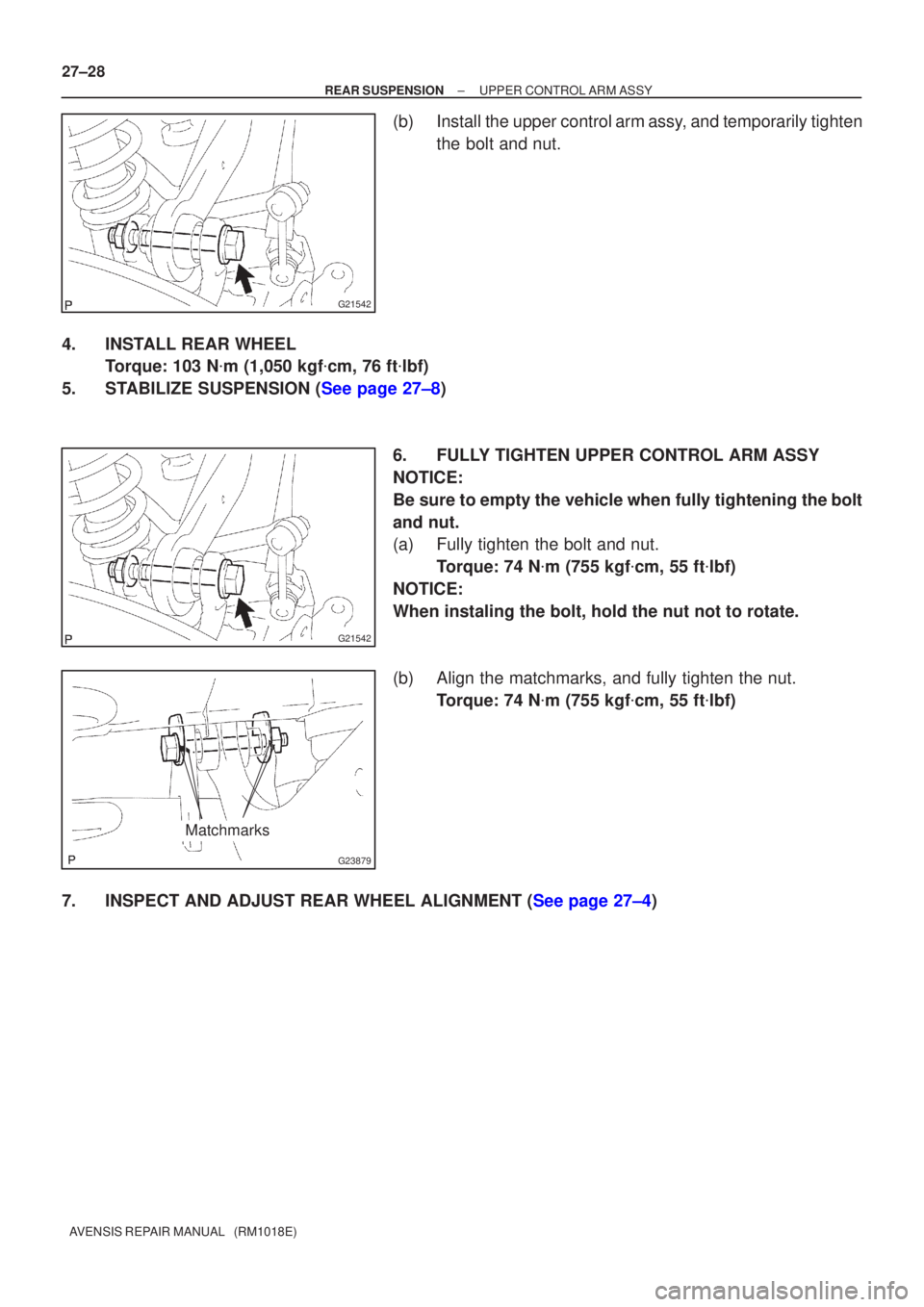
(b) Install the upper control arm assy, and temporarily tighten the bolt and nut.
4. INSTALL REAR WHEEL Torque: 103 N �m (1,050 kgf �cm, 76 ft �lbf)
5.STABILIZE SUSPENSION (See page 27±8)
6. FULLY TIGHTEN UPPER CONTROL ARM ASSY
NOTICE:
Be sure to empty the vehicle when fully tightening the bolt
and nut.
(a) Fully tighten the bolt and nut.Torque: 74 N �m (755 kgf �cm, 55 ft �lbf)
NOTICE:
When instaling the bolt, hold the nut not to rotate.
(b) Align the matchmarks, and fully tighten the nut. Torque: 74 N �m (755 kgf �cm, 55 ft �lbf)
7.INSPECT AND ADJUST REAR WHEEL ALIGNMENT (See page 27±4)