2600L±02
F44617
Front:AB
F44618
Rear:
C D
SA3213
A
D B
Front
C
F44619
26±6
±
FRONT SUSPENSION FRONT WHEEL ALIGNMENT
AVENSIS REPAIR MANUAL (RM1018E)
FRONT WHEEL ALIGNMENT
ADJUSTMENT
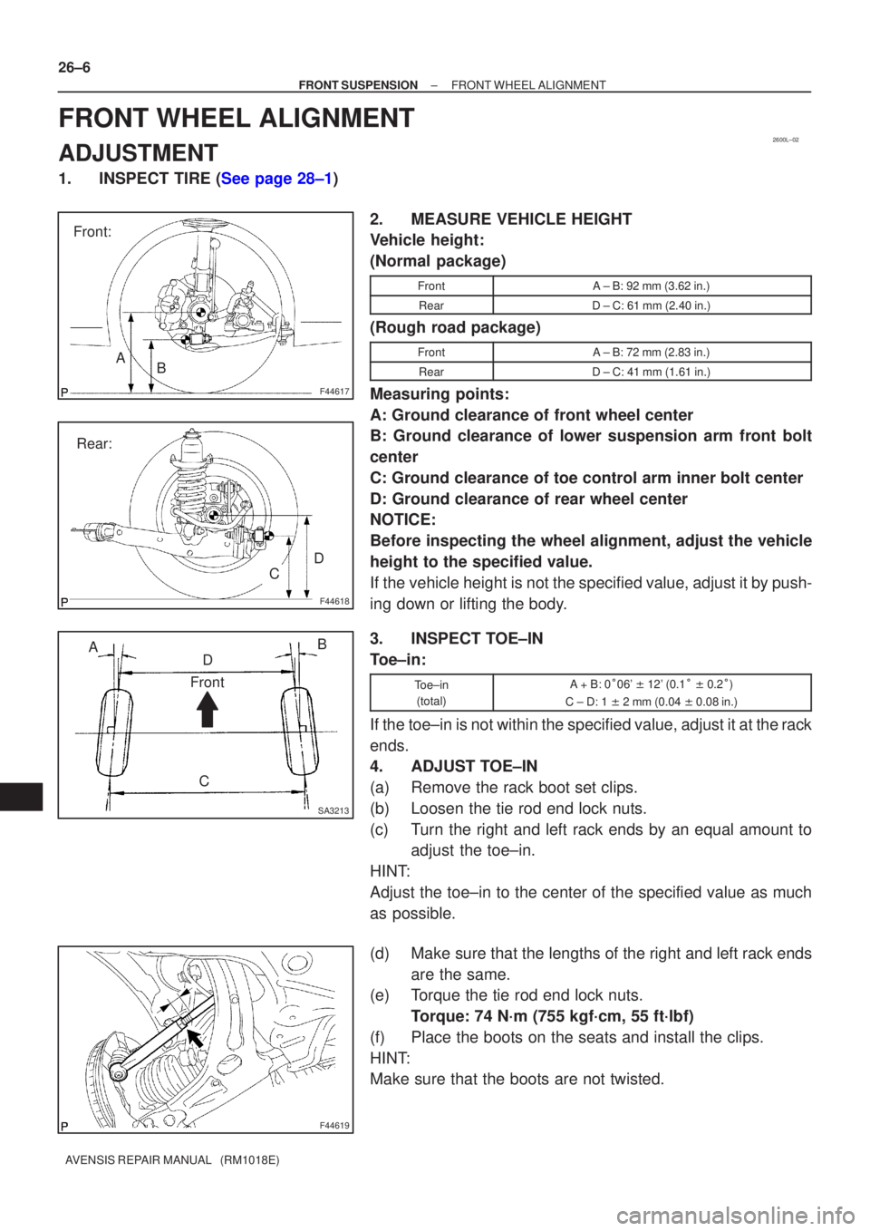
1.INSPECT TIRE (See page 28±1) 2. MEASURE VEHICLE HEIGHT
Vehicle height:
(Normal package)
FrontA ± B: 92 mm (3.62 in.)
RearD ± C: 61 mm (2.40 in.)
(Rough road package)
FrontA ± B: 72 mm (2.83 in.)
RearD ± C: 41 mm (1.61 in.)
Measuring points:
A: Ground clearance of front wheel center
B: Ground clearance of lower suspension arm front bolt
center
C: Ground clearance of toe control arm inner bolt center
D: Ground clearance of rear wheel center
NOTICE:
Before inspecting the wheel alignment, adjust the vehicle
height to the specified value.
If the vehicle height is not the specified value, adjust it by push-
ing down or lifting the body.
3. INSPECT TOE±IN
Toe±in:
Toe±in(total)A + B: 0 �06' � 12' (0.1 � � 0.2 �)
C ± D: 1 � 2 mm (0.04 � 0.08 in.)
If the toe±in is not within the specified value, adjust it at the rack
ends.
4. ADJUST TOE±IN
(a) Remove the rack boot set clips.
(b) Loosen the tie rod end lock nuts.
(c) Turn the right and left rack ends by an equal amount to
adjust the toe±in.
HINT:
Adjust the toe±in to the center of the specified value as much
as possible.
(d) Make sure that the lengths of the right and left rack ends are the same.
(e) Torque the tie rod end lock nuts.
Torque: 74 N´m (755 kgf´cm, 55 ft´lbf)
(f) Place the boots on the seats and install the clips.
HINT:
Make sure that the boots are not twisted.
A09656
A79144
A80110
±
FUEL INJECTOR ASSY(1CD±FTV)
11±61
AVENSIS REPAIR MANUAL (RM1018E)
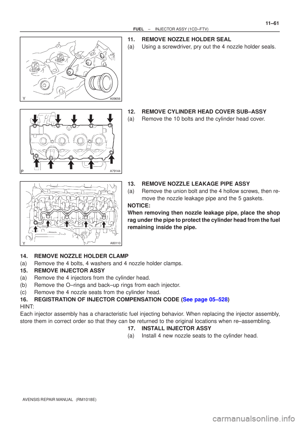
11.REMOVE NOZZLE HOLDER SEAL
(a)Using a screwdriver, pry out the 4 nozzle holder seals.
12.REMOVE CYLINDER HEAD COVER SUB±ASSY
(a)Remove the 10 bolts and the cylinder head cover.
13.REMOVE NOZZLE LEAKAGE PIPE ASSY
(a)Remove the union bolt and the 4 hollow screws, then re-
move the nozzle leakage pipe and the 5 gaskets.
NOTICE:
When removing then nozzle leakage pipe, place the shop
rag under the pipe to protect the cylinder head from the fuel
remaining inside the pipe.
14.REMOVE NOZZLE HOLDER CLAMP
(a)Remove the 4 bolts, 4 washers and 4 nozzle holder clamps.
15.REMOVE INJECTOR ASSY
(a)Remove the 4 injectors from the cylinder head.
(b)Remove the O±rings and back±up rings from each injector.
(c)Remove the 4 nozzle seats from the cylinder head.
16.REGISTRATION OF INJECTOR COMPENSATION CODE (See page 05±528)
HINT:
Each injector assembly has a characteristic fuel injecting behavior. When replacing the injector assembly,
store them in correct order so that they can be returned to the original\
locations when re±assembling. 17. INSTALL INJECTOR ASSY
(a) Install 4 new nozzle seats to the cylinder head.