Page 19 of 1690
670S8±01
������I35168
������I35169
(2)
(1)
(3)
H02440
Riveter
Mandrel
67±10
±
AUDIO & VISUAL SYSTEM FRONT NO.1 SPEAKER ASSY
AVENSIS REPAIR MANUAL (RM1018E)
FRONT NO.1 SPEAKER ASSY
REPLACEMENT
1. REMOVE REAR DOOR WINDOW REGULATOR HANDLE ASSY (W/O POWER WINDOW) (See page 75±8)
2.REMOVE FRONT DOOR LOWER FRAME BRACKET GARNISH LH (See page 75±8)
3.REMOVE FRONT DOOR TRIM BASE LH (See page 75±8)
4.REMOVE FUEL LID OPENER SWITCH (See page 75±8)
5. REMOVE POWER WINDOW REGULATOR SWITCH ASSY (W/ POWER WINDOW) (See page 75±8)
6.REMOVE FRONT DOOR TRIM BOARD SUB±ASSY LH (See page 75±8)
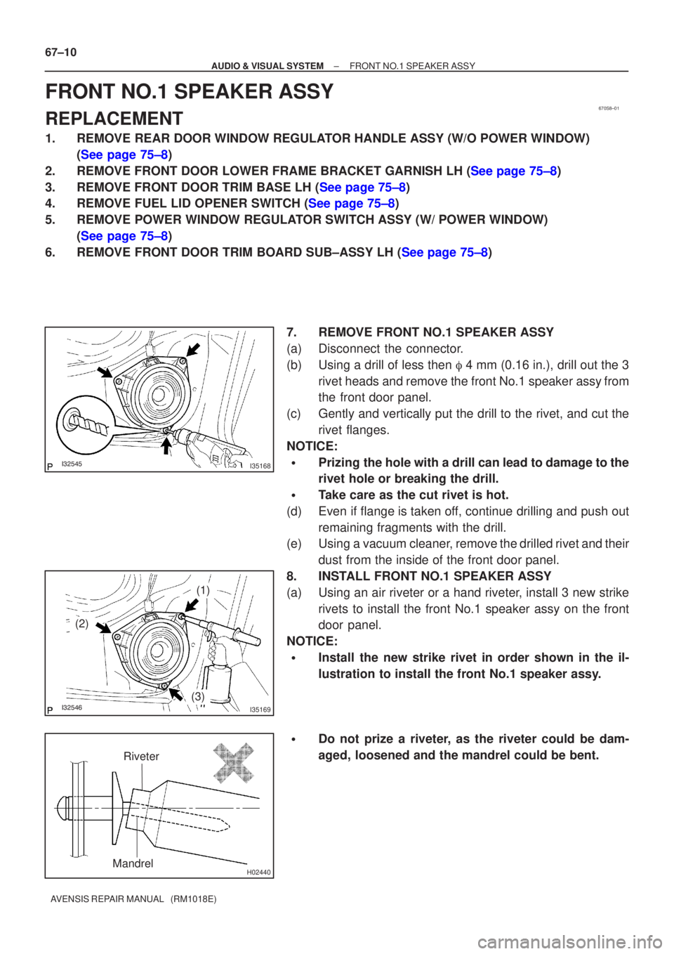
7. REMOVE FRONT NO.1 SPEAKER ASSY
(a) Disconnect the connector.
(b) Using a drill of less then � 4 mm (0.16 in.), drill out the 3
rivet heads and remove the front No.1 speaker assy from
the front door panel.
(c) Gently and vertically put the drill to the rivet, and cut the rivet flanges.
NOTICE:
�Prizing the hole with a drill can lead to damage to the
rivet hole or breaking the drill.
�Take care as the cut rivet is hot.
(d) Even if flange is taken off, continue drilling and push out remaining fragments with the drill.
(e) Using a vacuum cleaner, remove the drilled rivet and their
dust from the inside of the front door panel.
8. INSTALL FRONT NO.1 SPEAKER ASSY
(a) Using an air riveter or a hand riveter, install 3 new strike rivets to install the front No.1 speaker assy on the front
door panel.
NOTICE:
�Install the new strike rivet in order shown in the il-
lustration to install the front No.1 speaker assy.
�Do not prize a riveter, as the riveter could be dam-
aged, loosened and the mandrel could be bent.
Page 30 of 1690
670SA±01
������I35188
������I35189
(2)
(1)
(3)
H02440
Riveter
Mandrel
±
AUDIO & VISUAL SYSTEM REAR SPEAKER ASSY
67±13
AVENSIS REPAIR MANUAL (RM1018E)
REAR SPEAKER ASSY
REPLACEMENT
1.REMOVE REAR DOOR WINDOW REGULATOR HANDLE ASSY (See page 75±22)
2.REMOVE REAR DOOR TRIM BASE LH (See page 75±22)
3. REMOVE POWER WINDOW REGULATOR SWITCH ASSY REAR (W/ POWER WINDOW)
(See page 75±22)
4.REMOVE REAR DOOR TRIM BOARD SUB±ASSY LH (See page 75±22)
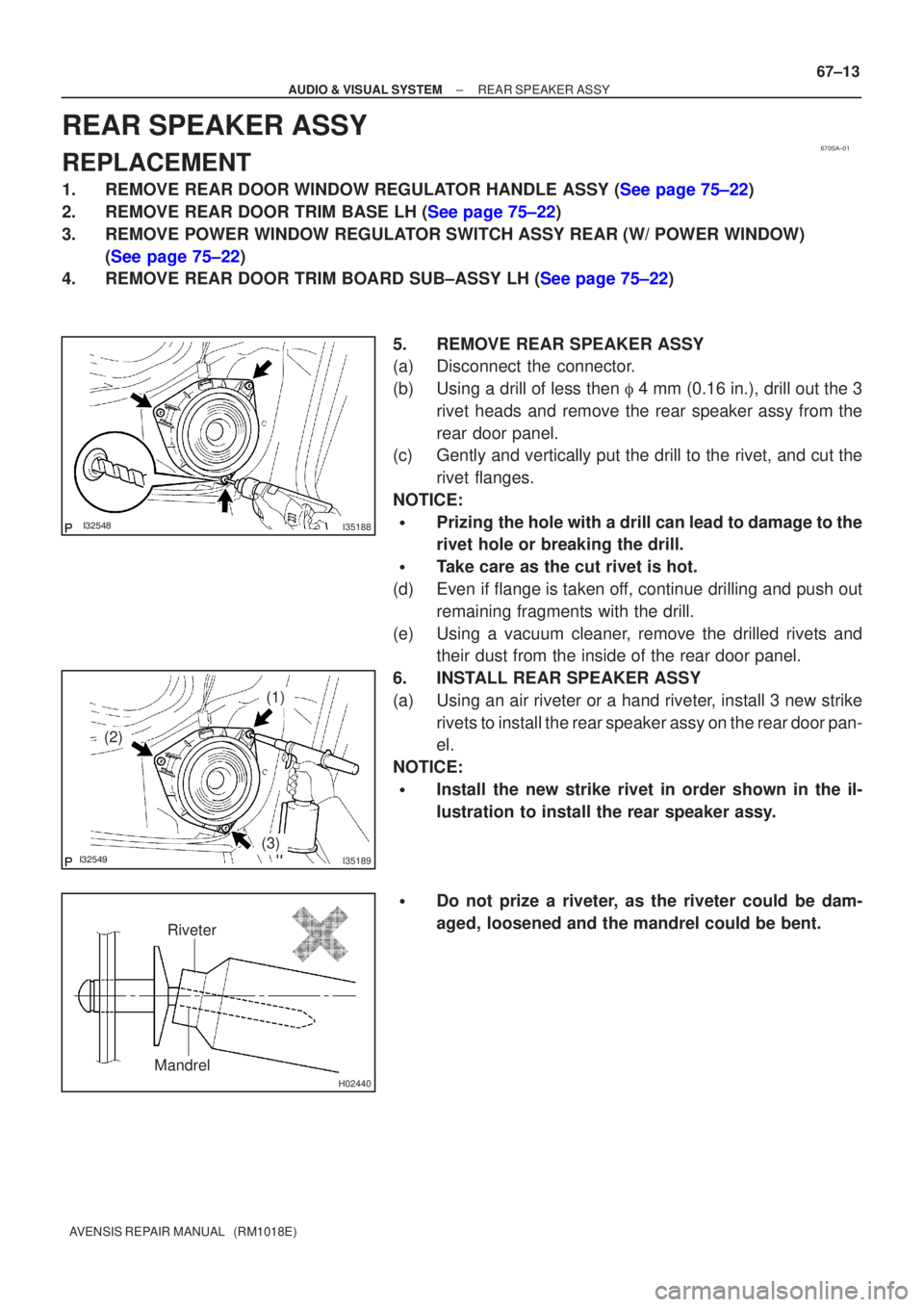
5. REMOVE REAR SPEAKER ASSY
(a) Disconnect the connector.
(b) Using a drill of less then � 4 mm (0.16 in.), drill out the 3
rivet heads and remove the rear speaker assy from the
rear door panel.
(c) Gently and vertically put the drill to the rivet, and cut the
rivet flanges.
NOTICE:
�Prizing the hole with a drill can lead to damage to the
rivet hole or breaking the drill.
�Take care as the cut rivet is hot.
(d) Even if flange is taken off, continue drilling and push out remaining fragments with the drill.
(e) Using a vacuum cleaner, remove the drilled rivets and their dust from the inside of the rear door panel.
6. INSTALL REAR SPEAKER ASSY
(a) Using an air riveter or a hand riveter, install 3 new strike rivets to install the rear speaker assy on the rear door pan-
el.
NOTICE:
�Install the new strike rivet in order shown in the il-
lustration to install the rear speaker assy.
�Do not prize a riveter, as the riveter could be dam-
aged, loosened and the mandrel could be bent.
Page 32 of 1690
670SB±01
I36707
±
AUDIO & VISUAL SYSTEM REAR SPEAKER ASSY NO.2
67±15
AVENSIS REPAIR MANUAL (RM1018E)
REAR SPEAKER ASSY NO.2
REPLACEMENT
1. REMOVE REAR DOOR WINDOW REGULATOR HANDLE ASSY (W/O POWER WINDOW)
(See page 75±22)
2. REMOVE POWER WINDOW REGULATOR SWITCH ASSY REAR (W/ POWER WINDOW) (See page 75±22)
3.REMOVE REAR DOOR TRIM BASE LH (See page 75±22)
4.REMOVE REAR DOOR TRIM BOARD SUB±ASSY LH (See page 75±22)
5. REMOVE REAR SPEAKER ASSY NO.2
(a) Disconnect the connector.
(b) Remove the screw and the rear No.2 speaker assy.
Page 33 of 1690
670SL±01
BE4029
Tester Probe
Tin FoilHeat Wire
E32576
BE0150
Repair Point
Masking TapeBroken
Wire
BE0151
Repair PointFine Tip Brush
Glass
± AUDIO & VISUAL SYSTEMWINDOW GLASS (ANTENNA WIRE)
67±33
AVENSIS REPAIR MANUAL (RM1018E)
WINDOW GLASS (ANTENNA WIRE)
REPAIR
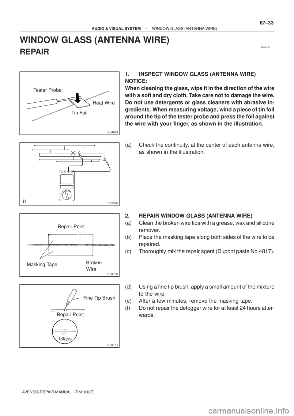
1. INSPECT WINDOW GLASS (ANTENNA WIRE)
NOTICE:
When cleaning the glass, wipe it in the direction of the wire
with a soft and dry cloth. Take care not to damage the wire.
Do not use detergents or glass cleaners with abrasive in-
gredients. When measuring voltage, wind a piece of tin foil
around the tip of the tester probe and press the foil against
the wire with your finger, as shown in the illustration.
(a) Check the continuity, at the center of each antenna wire,
as shown in the illustration.
2. REPAIR WINDOW GLASS (ANTENNA WIRE)
(a) Clean the broken wire tips with a grease, wax and silicone
remover.
(b) Place the masking tape along both sides of the wire to be
repaired.
(c) Thoroughly mix the repair agent (Dupont paste No.4817).
(d) Using a fine tip brush, apply a small amount of the mixture
to the wire.
(e) After a few minutes, remove the masking tape.
(f) Do not repair the defogger wire for at least 24 hours after-
wards.
Page 313 of 1690
750MV±01
B67988
Front Door Glass
Sub±assy LH Front Door Glass Run LH
Front Door Frame Sub±assy Rear Lower LH
8.0 (82, 71 in.´lbf)
Front Door Glass Weatherstrip Inner LH
Front Door Trim Board Sub±assy LH Front Door Armrest
Base Panel Upper
Courtesy Lamp
: Specified torque
N´m (kgf´cm, ft´lbf)Front No. 1 Speaker Assy Front Door Inside Handle Sub±assy LH
Fuel Lid Opener Switch
Front Door Trim Base LHClip
Power Window Regulator
Switch Assy Front Door Armrest Base Panel Upper
w/o Rear Power Window
Front Door Window Regulator
Sub±assy LH
8.0 (82, 71 in.´lbf)
Power Window Regulator
Master Switch Assy
Rivet
Non±reusable part ��
5.5 (56, 49 in.´lbf)
75±4
± ENGINE HOOD/DOORFRONT DOOR
AVENSIS REPAIR MANUAL (RM1018E)
FRONT DOOR
COMPONENTS
Page 318 of 1690
B70388
B66971: Clip
Protective
TapeProtective
Tape
Screw
BoltCushion Rubber
B70121
B68930
Claw A
: Claw 1
2
± ENGINE HOOD/DOORFRONT DOOR
75±9
AVENSIS REPAIR MANUAL (RM1018E)
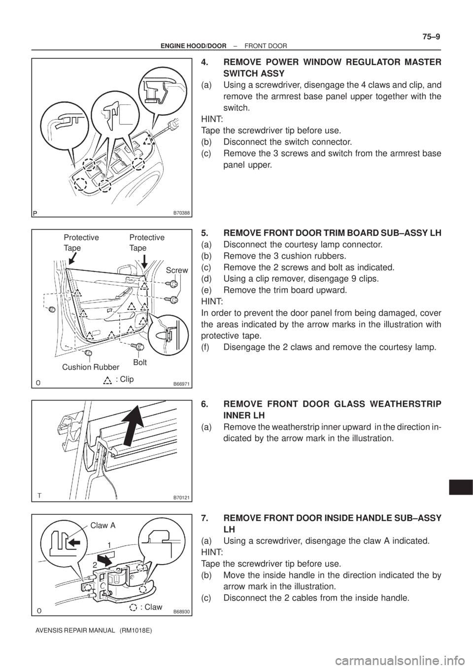
4. REMOVE POWER WINDOW REGULATOR MASTER
SWITCH ASSY
(a) Using a screwdriver, disengage the 4 claws and clip, and
remove the armrest base panel upper together with the
switch.
HINT:
Tape the screwdriver tip before use.
(b) Disconnect the switch connector.
(c) Remove the 3 screws and switch from the armrest base
panel upper.
5. REMOVE FRONT DOOR TRIM BOARD SUB±ASSY LH
(a) Disconnect the courtesy lamp connector.
(b) Remove the 3 cushion rubbers.
(c) Remove the 2 screws and bolt as indicated.
(d) Using a clip remover, disengage 9 clips.
(e) Remove the trim board upward.
HINT:
In order to prevent the door panel from being damaged, cover
the areas indicated by the arrow marks in the illustration with
protective tape.
(f) Disengage the 2 claws and remove the courtesy lamp.
6. REMOVE FRONT DOOR GLASS WEATHERSTRIP
INNER LH
(a) Remove the weatherstrip inner upward in the direction in-
dicated by the arrow mark in the illustration.
7. REMOVE FRONT DOOR INSIDE HANDLE SUB±ASSY
LH
(a) Using a screwdriver, disengage the claw A indicated.
HINT:
Tape the screwdriver tip before use.
(b) Move the inside handle in the direction indicated the by
arrow mark in the illustration.
(c) Disconnect the 2 cables from the inside handle.
Page 320 of 1690
B62422
B62423
12
B66968
B61434
������B68932Hole Plug
± ENGINE HOOD/DOORFRONT DOOR
75±11
AVENSIS REPAIR MANUAL (RM1018E)
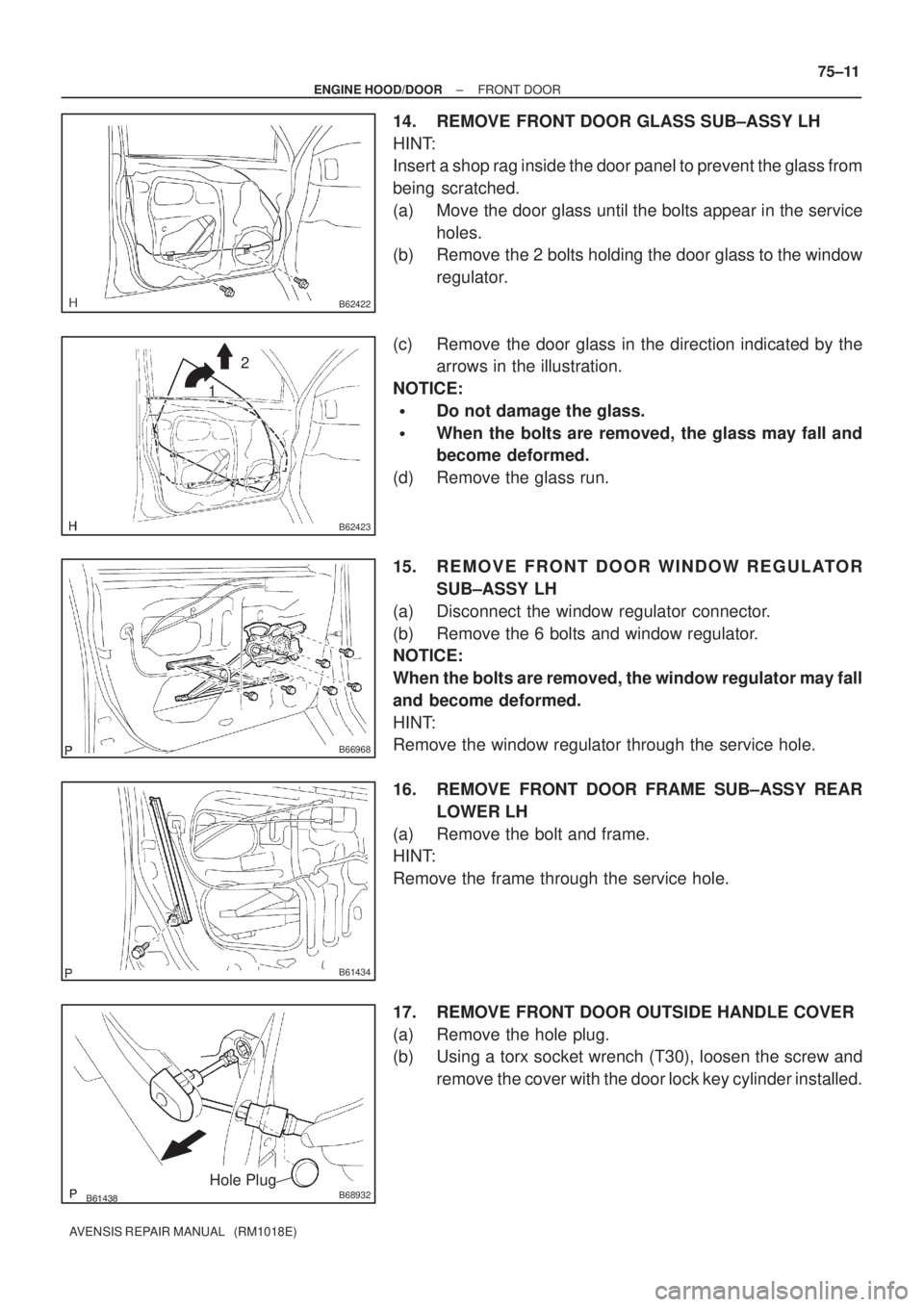
14. REMOVE FRONT DOOR GLASS SUB±ASSY LH
HINT:
Insert a shop rag inside the door panel to prevent the glass from
being scratched.
(a) Move the door glass until the bolts appear in the service
holes.
(b) Remove the 2 bolts holding the door glass to the window
regulator.
(c) Remove the door glass in the direction indicated by the
arrows in the illustration.
NOTICE:
�Do not damage the glass.
�When the bolts are removed, the glass may fall and
become deformed.
(d) Remove the glass run.
15. REMOVE FRONT DOOR WINDOW REGULATOR
SUB±ASSY LH
(a) Disconnect the window regulator connector.
(b) Remove the 6 bolts and window regulator.
NOTICE:
When the bolts are removed, the window regulator may fall
and become deformed.
HINT:
Remove the window regulator through the service hole.
16. REMOVE FRONT DOOR FRAME SUB±ASSY REAR
LOWER LH
(a) Remove the bolt and frame.
HINT:
Remove the frame through the service hole.
17. REMOVE FRONT DOOR OUTSIDE HANDLE COVER
(a) Remove the hole plug.
(b) Using a torx socket wrench (T30), loosen the screw and
remove the cover with the door lock key cylinder installed.
Page 321 of 1690
B66894
B56613
1
2
B70122
Screw
B57102
B68928
75±12
± ENGINE HOOD/DOORFRONT DOOR
AVENSIS REPAIR MANUAL (RM1018E)
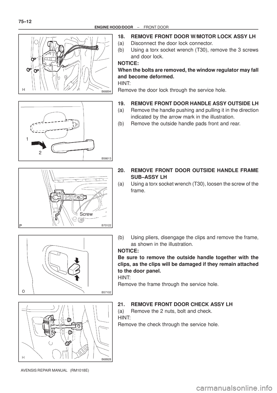
18. REMOVE FRONT DOOR W/MOTOR LOCK ASSY LH
(a) Disconnect the door lock connector.
(b) Using a torx socket wrench (T30), remove the 3 screws
and door lock.
NOTICE:
When the bolts are removed, the window regulator may fall
and become deformed.
HINT:
Remove the door lock through the service hole.
19. REMOVE FRONT DOOR HANDLE ASSY OUTSIDE LH
(a) Remove the handle pushing and pulling it in the direction
indicated by the arrow mark in the illustration.
(b) Remove the outside handle pads front and rear.
20. REMOVE FRONT DOOR OUTSIDE HANDLE FRAME
SUB±ASSY LH
(a) Using a torx socket wrench (T30), loosen the screw of the
frame.
(b) Using pliers, disengage the clips and remove the frame,
as shown in the illustration.
NOTICE:
Be sure to remove the outside handle together with the
clips, as the clips will be damaged if they remain attached
to the door panel.
HINT:
Remove the frame through the service hole.
21. REMOVE FRONT DOOR CHECK ASSY LH
(a) Remove the 2 nuts, bolt and check.
HINT:
Remove the check through the service hole.