Page 43 of 1690
320W3±01
F45167
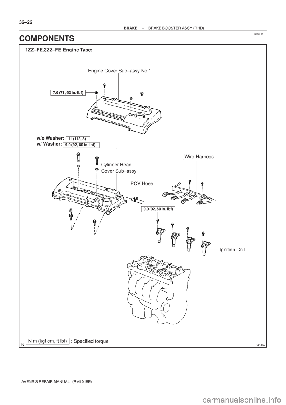
Engine Cover Sub±assy No.1
1ZZ±FE,3ZZ±FE Engine Type:
Wire Harness
Ignition Coil Cylinder Head
Cover Sub±assy
7.0 (71, 62 in.�lbf)
PCV Hose
N�m (kgf�cm, ft�lbf)
: Specified torquex8 w/o Washer:
w/ Washer:
11 (113, 8)
9.0 (92, 80 in.�lbf)
9.0 (92, 80 in.�lbf)
32±22
± BRAKEBRAKE BOOSTER ASSY (RHD)
AVENSIS REPAIR MANUAL (RM1018E)
COMPONENTS
Page 46 of 1690
320W4±01
G24211
F42291
±
BRAKE BRAKE BOOSTER ASSY (RHD)
32±25
AVENSIS REPAIR MANUAL (RM1018E)
REPLACEMENT
NOTICE:
Do not adjust the brake booster push rod.
1. DRAIN BRAKE FLUID
NOTICE:
Wash the brake fluid off immediately if it adheres to any painted surface\
.
2.REMOVE BRAKE MASTER CYLINDER SUB±ASSY (See page 32±13)
(a) w/o VSC:
SST 09023±00100
(b) w/ VSC: SST 09023±38400
3.REMOVE CLUTCH MASTER CYLINDER ASSY (M/T TRANSAXLE) (See page 42±13) SST 09023±00100
4. REMOVE ENGINE ASSEMBLY WITH TRANSAXLE (1AZ±FSE ENGINE TYPE) (See page 14±204)
5. REMOVE ENGINE COVER NO.1
6.REMOVE IGNITION COIL ASSY (GASOLINE ENGINE TYPE) (See page 14±81)
7.REMOVE CYLINDER HEAD COVER SUB±ASSY (GASOLINE ENGINE TYPE) (See page 14±81)
8.REMOVE TIMING BELT NO.2 COVER (DIESEL ENGINE TYPE) (See page 14±307)
9.REMOVE CYLINDER HEAD COVER SUB±ASSY (DIESEL ENGINE TYPE) (See page 14±318)
10.REMOVE INJECTOR ASSY (DIESEL ENGINE TYPE) (See page 14±318)
11. REMOVE FRONT WHEEL RH
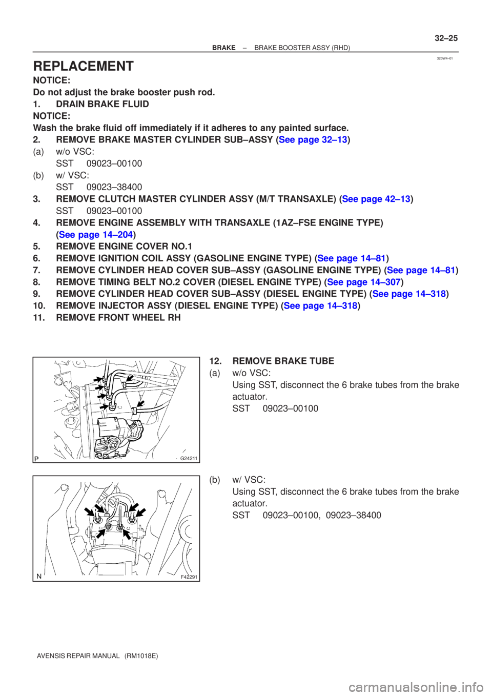
12. REMOVE BRAKE TUBE
(a) w/o VSC:Using SST, disconnect the 6 brake tubes from the brake
actuator.
SST 09023±00100
(b) w/ VSC: Using SST, disconnect the 6 brake tubes from the brake
actuator.
SST 09023±00100, 09023±38400
Page 52 of 1690
F45057
w/o VSC:
w/ VSC:
To Master
Cylinder Rear
To
Master
Cylinder
Front
To Rear Wheel
RH
To Front Wheel LH
To Front Wheel RH
To Rear Wheel
LH
A
To
Master
Cylinder
FrontTo Master
Cylinder
Rear
To Rear
Wheel RH
To Front Wheel LHTo Front Wheel RH
To Rear
Wheel LH
AA
AA
BB
C80806
±
BRAKE BRAKE BOOSTER ASSY (RHD)
32±31
AVENSIS REPAIR MANUAL (RM1018E)
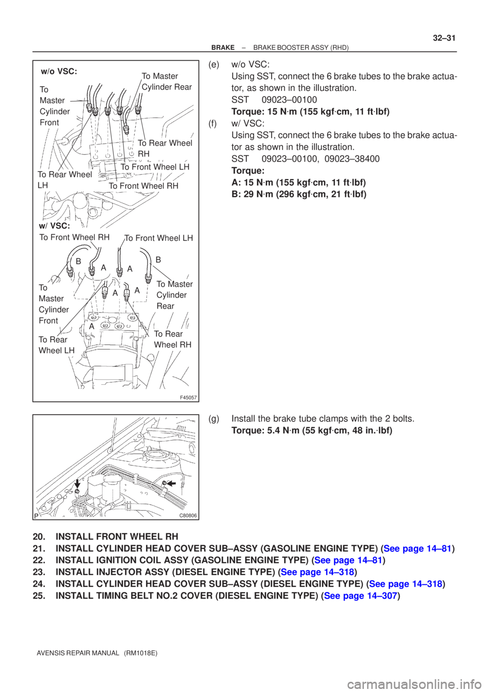
(e) w/o VSC:
Using SST, connect the 6 brake tubes to the brake actua-
tor, as shown in the illustration.
SST 09023±00100
Torque: 15 N �m (155 kgf �cm, 11 ft �lbf)
(f) w/ VSC: Using SST, connect the 6 brake tubes to the brake actua-
tor as shown in the illustration.
SST 09023±00100, 09023±38400
Torque:
A: 15 N �m (155 kgf �cm, 11 ft �lbf)
B: 29 N �m (296 kgf �cm, 21 ft �lbf)
(g) Install the brake tube clamps with the 2 bolts. Torque: 5.4 N �m (55 kgf �cm, 48 in. �lbf)
20. INSTALL FRONT WHEEL RH
21.INSTALL CYLINDER HEAD COVER SUB±ASSY (GASOLINE ENGINE TYPE) (See page 14±81)
22.INSTALL IGNITION COIL ASSY (GASOLINE ENGINE TYPE) (See page 14±81)
23.INSTALL INJECTOR ASSY (DIESEL ENGINE TYPE) (See page 14±318)
24.INSTALL CYLINDER HEAD COVER SUB±ASSY (DIESEL ENGINE TYPE) (See page 14±318)
25.INSTALL TIMING BELT NO.2 COVER (DIESEL ENGINE TYPE) (See page 14±307)
Page 92 of 1690
320W2±01
G24251
Vacuum Hose
Oil Hose
F45364
F08966
F08967
± BRAKEVACUUM PUMP ASSY (1CD±FTV)
32±35
AVENSIS REPAIR MANUAL (RM1018E)
OVERHAUL
1. REMOVE AIR CLEANER CAP SUB±ASSY
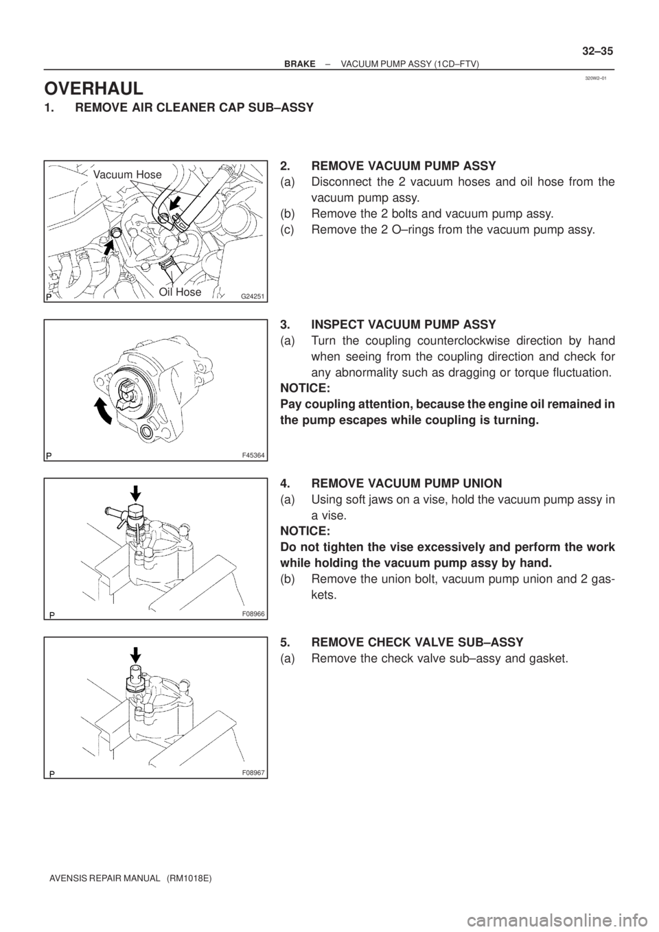
2. REMOVE VACUUM PUMP ASSY
(a) Disconnect the 2 vacuum hoses and oil hose from the
vacuum pump assy.
(b) Remove the 2 bolts and vacuum pump assy.
(c) Remove the 2 O±rings from the vacuum pump assy.
3. INSPECT VACUUM PUMP ASSY
(a) Turn the coupling counterclockwise direction by hand
when seeing from the coupling direction and check for
any abnormality such as dragging or torque fluctuation.
NOTICE:
Pay coupling attention, because the engine oil remained in
the pump escapes while coupling is turning.
4. REMOVE VACUUM PUMP UNION
(a) Using soft jaws on a vise, hold the vacuum pump assy in
a vise.
NOTICE:
Do not tighten the vise excessively and perform the work
while holding the vacuum pump assy by hand.
(b) Remove the union bolt, vacuum pump union and 2 gas-
kets.
5. REMOVE CHECK VALVE SUB±ASSY
(a) Remove the check valve sub±assy and gasket.
Page 94 of 1690
F05383
Air
Hose Side Vacuum Pump Side
Air
F08981
F08982
New O±Ring
F08970
± BRAKEVACUUM PUMP ASSY (1CD±FTV)
32±37
AVENSIS REPAIR MANUAL (RM1018E)
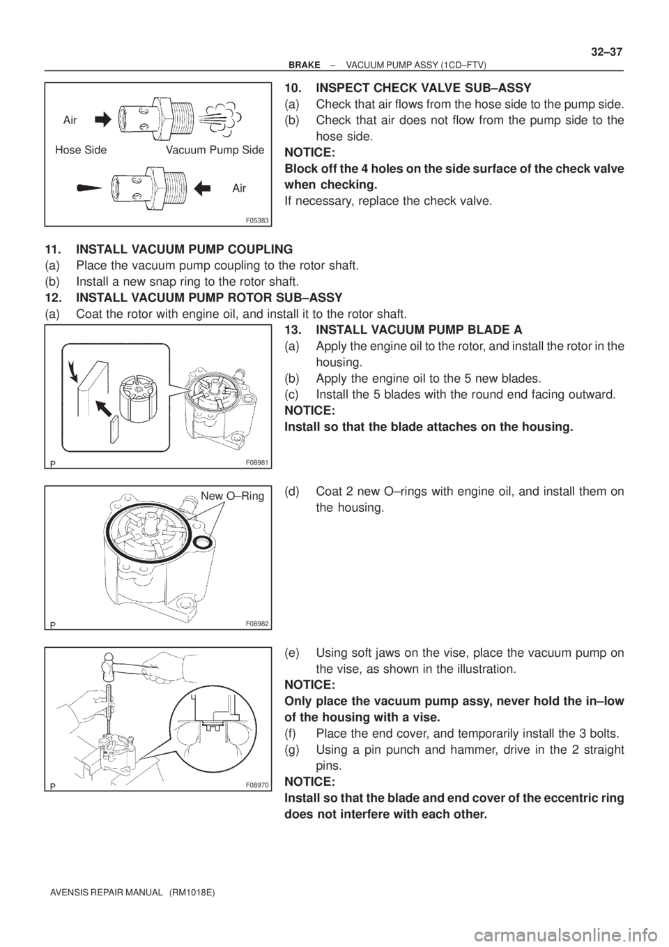
10. INSPECT CHECK VALVE SUB±ASSY
(a) Check that air flows from the hose side to the pump side.
(b) Check that air does not flow from the pump side to the
hose side.
NOTICE:
Block off the 4 holes on the side surface of the check valve
when checking.
If necessary, replace the check valve.
11. INSTALL VACUUM PUMP COUPLING
(a) Place the vacuum pump coupling to the rotor shaft.
(b) Install a new snap ring to the rotor shaft.
12. INSTALL VACUUM PUMP ROTOR SUB±ASSY
(a) Coat the rotor with engine oil, and install it to the rotor shaft.
13. INSTALL VACUUM PUMP BLADE A
(a) Apply the engine oil to the rotor, and install the rotor in the
housing.
(b) Apply the engine oil to the 5 new blades.
(c) Install the 5 blades with the round end facing outward.
NOTICE:
Install so that the blade attaches on the housing.
(d) Coat 2 new O±rings with engine oil, and install them on
the housing.
(e) Using soft jaws on the vise, place the vacuum pump on
the vise, as shown in the illustration.
NOTICE:
Only place the vacuum pump assy, never hold the in±low
of the housing with a vise.
(f) Place the end cover, and temporarily install the 3 bolts.
(g) Using a pin punch and hammer, drive in the 2 straight
pins.
NOTICE:
Install so that the blade and end cover of the eccentric ring
does not interfere with each other.
Page 96 of 1690
G24250
Vacuum HoseNew O±Ring
Oil Hose
F45366
Vacuum Gauge
± BRAKEVACUUM PUMP ASSY (1CD±FTV)
32±39
AVENSIS REPAIR MANUAL (RM1018E)
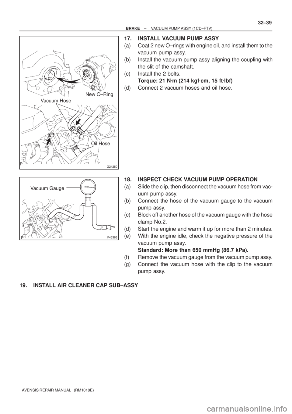
17. INSTALL VACUUM PUMP ASSY
(a) Coat 2 new O±rings with engine oil, and install them to the
vacuum pump assy.
(b) Install the vacuum pump assy aligning the coupling with
the slit of the camshaft.
(c) Install the 2 bolts.
Torque: 21 N�m (214 kgf�cm, 15 ft�lbf)
(d) Connect 2 vacuum hoses and oil hose.
18. INSPECT CHECK VACUUM PUMP OPERATION
(a) Slide the clip, then disconnect the vacuum hose from vac-
uum pump assy.
(b) Connect the hose of the vacuum gauge to the vacuum
pump assy.
(c) Block off another hose of the vacuum gauge with the hose
clamp No.2.
(d) Start the engine and warm it up for more than 2 minutes.
(e) With the engine idle, check the negative pressure of the
vacuum pump assy.
Standard: More than 650 mmHg (86.7 kPa).
(f) Remove the vacuum gauge from the vacuum pump assy.
(g) Connect the vacuum hose with the clip to the vacuum
pump assy.
19. INSTALL AIR CLEANER CAP SUB±ASSY
Page 122 of 1690
4200B±04
±
CLUTCH CLUTCH SYSTEM (MTM)
42±1
AVENSIS REPAIR MANUAL (RM1018E)
CLUTCH SYSTEM (MTM)
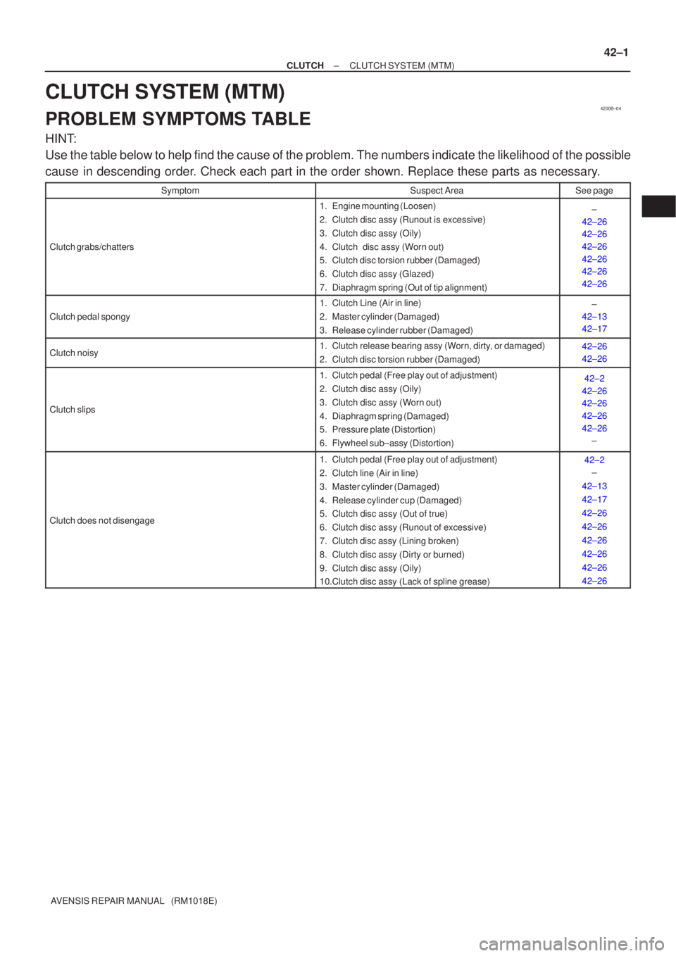
PROBLEM SYMPTOMS TABLE
HINT:
Use the table below to help find the cause of the problem. The numbers indi\
cate the likelihood of the possible
cause in descending order. Check each part in the order shown. Replace these parts as necessary.
SymptomSuspect AreaSee page
Clutch grabs/chatters
1. Engine mounting (Loosen)
2. Clutch disc assy (Runout is excessive)
3. Clutch disc assy (Oily)
4. Clutch disc assy (Worn out)
5. Clutch disc torsion rubber (Damaged)
6. Clutch disc assy (Glazed)
7. Diaphragm spring (Out of tip alignment)±
42±26
42±26
42±26
42±26
42±26
42±26
Clutch pedal spongy
1. Clutch Line (Air in line)
2. Master cylinder (Damaged)
3. Release cylinder rubber (Damaged)±
42±13
42±17
Clutch noisy1. Clutch release bearing assy (Worn, dirty, or damaged)
2. Clutch disc torsion rubber (Damaged)42±26
42±26
Clutch slips
1. Clutch pedal (Free play out of adjustment)
2. Clutch disc assy (Oily)
3. Clutch disc assy (Worn out)
4. Diaphragm spring (Damaged)
5. Pressure plate (Distortion)
6. Flywheel sub±assy (Distortion)42±2
42±26
42±26
42±26
42±26 ±
Clutch does not disengage
1. Clutch pedal (Free play out of adjustment)
2. Clutch line (Air in line)
3. Master cylinder (Damaged)
4. Release cylinder cup (Damaged)
5. Clutch disc assy (Out of true)
6. Clutch disc assy (Runout of excessive)
7. Clutch disc assy (Lining broken)
8. Clutch disc assy (Dirty or burned)
9. Clutch disc assy (Oily)
10.Clutch disc assy (Lack of spline grease)42±2
±
42±13
42±17
42±26
42±26
42±26
42±26
42±26
42±26
Page 127 of 1690
C62956
D30058
1CD±FTV Engine Type: Others:
Transaxle Side
������
D25281
AB
C62958
± CLUTCHCLUTCH UNIT (MTM)
42±27
AVENSIS REPAIR MANUAL (RM1018E)
8. REMOVE CLUTCH DISC ASSY
NOTICE:
Keep the lining part of the clutch disc assy, the pressure plate and surface of the flywheel sub±assy
away from oil and foreign attachment.
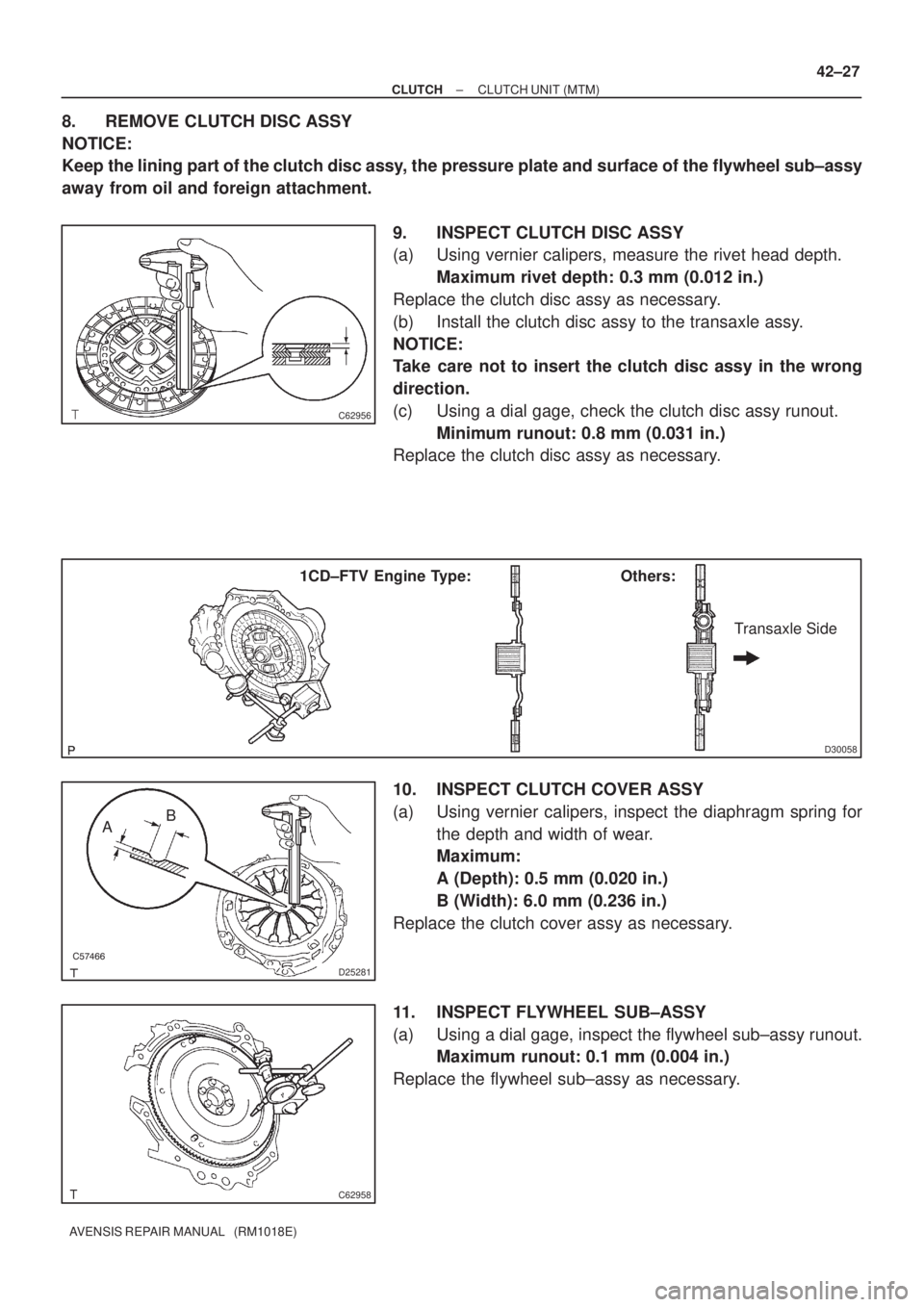
9. INSPECT CLUTCH DISC ASSY
(a) Using vernier calipers, measure the rivet head depth.
Maximum rivet depth: 0.3 mm (0.012 in.)
Replace the clutch disc assy as necessary.
(b) Install the clutch disc assy to the transaxle assy.
NOTICE:
Take care not to insert the clutch disc assy in the wrong
direction.
(c) Using a dial gage, check the clutch disc assy runout.
Minimum runout: 0.8 mm (0.031 in.)
Replace the clutch disc assy as necessary.
10. INSPECT CLUTCH COVER ASSY
(a) Using vernier calipers, inspect the diaphragm spring for
the depth and width of wear.
Maximum:
A (Depth): 0.5 mm (0.020 in.)
B (Width): 6.0 mm (0.236 in.)
Replace the clutch cover assy as necessary.
11. INSPECT FLYWHEEL SUB±ASSY
(a) Using a dial gage, inspect the flywheel sub±assy runout.
Maximum runout: 0.1 mm (0.004 in.)
Replace the flywheel sub±assy as necessary.