Page 12 of 1690
670S4±01
± AUDIO & VISUAL SYSTEMAUDIO & VISUAL SYSTEM
67±1
AVENSIS REPAIR MANUAL (RM1018E)
AUDIO & VISUAL SYSTEM
PRECAUTION
1. OBSERVE HANDLING AND OPERATIONAL PRECAUTIONS
(a) Please explain to the customer that when the negative terminal is disconnected from the battery, the
channel information memory of the AM/FM broadcast stations in the radio receiver is cleared. If neces-
sary, make a note of the recorded channel information before the negative terminal is disconnected,
then reset the information after the negative terminal is reconnected.
(b) The removal/installation of the radio receiver should be performed after all the cassette tapes and au-
dio CDs are ejected from the radio receiver.
HINT:
If the cassette tapes and the audio CDs cannot be ejected due to the malfunction of the radio receiver, do
not try to drag them out by force. Bring the vehicle to the repair plant.
(c) Fasten the earth bolt securely when the antenna cord is removed or installed.
HINT:
Failing to fasten the earth bolt securely causes noise at the time of radio wave reception.
(d) Do not touch the cone paper of the speaker.
Page 14 of 1690
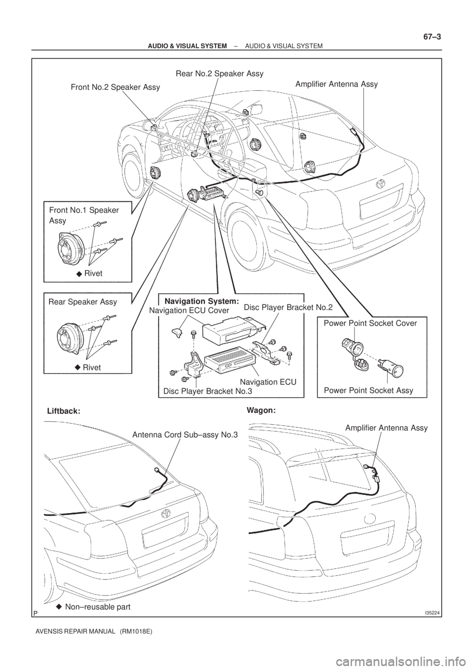
I35224
Front No.2 Speaker AssyAmplifier Antenna Assy
Front No.1 Speaker
Assy
Rear Speaker AssyNavigation System:
Disc Player Bracket No.2 Rivet
Navigation ECUPower Point Socket Cover
Power Point Socket Assy
Liftback:
Antenna Cord Sub±assy No.3Amplifier Antenna Assy Wagon:
Non±reusable part ��
Disc Player Bracket No.3
Rivet �
Rear No.2 Speaker Assy
Navigation ECU Cover
± AUDIO & VISUAL SYSTEMAUDIO & VISUAL SYSTEM
67±3
AVENSIS REPAIR MANUAL (RM1018E)
Page 19 of 1690

670S8±01
������I35168
������I35169
(2)
(1)
(3)
H02440
Riveter
Mandrel
67±10
±
AUDIO & VISUAL SYSTEM FRONT NO.1 SPEAKER ASSY
AVENSIS REPAIR MANUAL (RM1018E)
FRONT NO.1 SPEAKER ASSY
REPLACEMENT
1. REMOVE REAR DOOR WINDOW REGULATOR HANDLE ASSY (W/O POWER WINDOW) (See page 75±8)
2.REMOVE FRONT DOOR LOWER FRAME BRACKET GARNISH LH (See page 75±8)
3.REMOVE FRONT DOOR TRIM BASE LH (See page 75±8)
4.REMOVE FUEL LID OPENER SWITCH (See page 75±8)
5. REMOVE POWER WINDOW REGULATOR SWITCH ASSY (W/ POWER WINDOW) (See page 75±8)
6.REMOVE FRONT DOOR TRIM BOARD SUB±ASSY LH (See page 75±8)
7. REMOVE FRONT NO.1 SPEAKER ASSY
(a) Disconnect the connector.
(b) Using a drill of less then � 4 mm (0.16 in.), drill out the 3
rivet heads and remove the front No.1 speaker assy from
the front door panel.
(c) Gently and vertically put the drill to the rivet, and cut the rivet flanges.
NOTICE:
�Prizing the hole with a drill can lead to damage to the
rivet hole or breaking the drill.
�Take care as the cut rivet is hot.
(d) Even if flange is taken off, continue drilling and push out remaining fragments with the drill.
(e) Using a vacuum cleaner, remove the drilled rivet and their
dust from the inside of the front door panel.
8. INSTALL FRONT NO.1 SPEAKER ASSY
(a) Using an air riveter or a hand riveter, install 3 new strike rivets to install the front No.1 speaker assy on the front
door panel.
NOTICE:
�Install the new strike rivet in order shown in the il-
lustration to install the front No.1 speaker assy.
�Do not prize a riveter, as the riveter could be dam-
aged, loosened and the mandrel could be bent.
Page 20 of 1690
H02441
Riveter
Riveter
H02442
Riveter
± AUDIO & VISUAL SYSTEMFRONT NO.1 SPEAKER ASSY
67±11
AVENSIS REPAIR MANUAL (RM1018E)
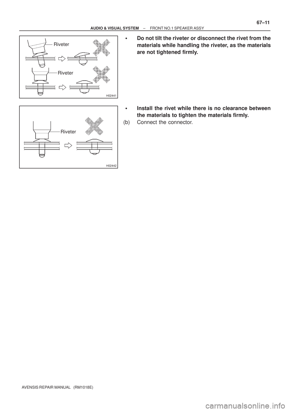
�Do not tilt the riveter or disconnect the rivet from the
materials while handling the riveter, as the materials
are not tightened firmly.
�Install the rivet while there is no clearance between
the materials to tighten the materials firmly.
(b) Connect the connector.
Page 21 of 1690
670S9±01
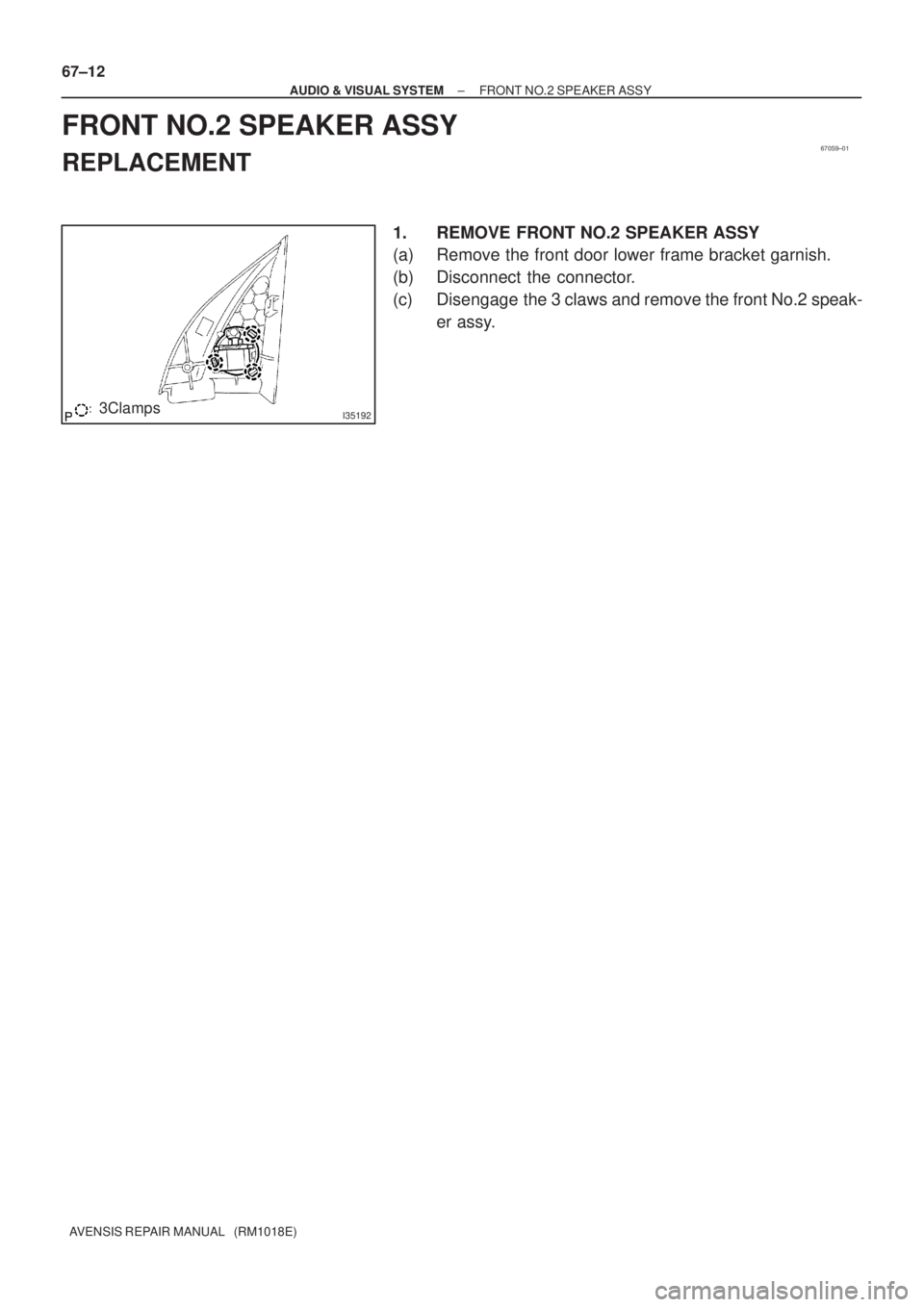
I351923Clamps 67±12
± AUDIO & VISUAL SYSTEMFRONT NO.2 SPEAKER ASSY
AVENSIS REPAIR MANUAL (RM1018E)
FRONT NO.2 SPEAKER ASSY
REPLACEMENT
1. REMOVE FRONT NO.2 SPEAKER ASSY
(a) Remove the front door lower frame bracket garnish.
(b) Disconnect the connector.
(c) Disengage the 3 claws and remove the front No.2 speak-
er assy.
Page 30 of 1690
670SA±01
������I35188
������I35189
(2)
(1)
(3)
H02440
Riveter
Mandrel
±
AUDIO & VISUAL SYSTEM REAR SPEAKER ASSY
67±13
AVENSIS REPAIR MANUAL (RM1018E)
REAR SPEAKER ASSY
REPLACEMENT
1.REMOVE REAR DOOR WINDOW REGULATOR HANDLE ASSY (See page 75±22)
2.REMOVE REAR DOOR TRIM BASE LH (See page 75±22)
3. REMOVE POWER WINDOW REGULATOR SWITCH ASSY REAR (W/ POWER WINDOW)
(See page 75±22)
4.REMOVE REAR DOOR TRIM BOARD SUB±ASSY LH (See page 75±22)
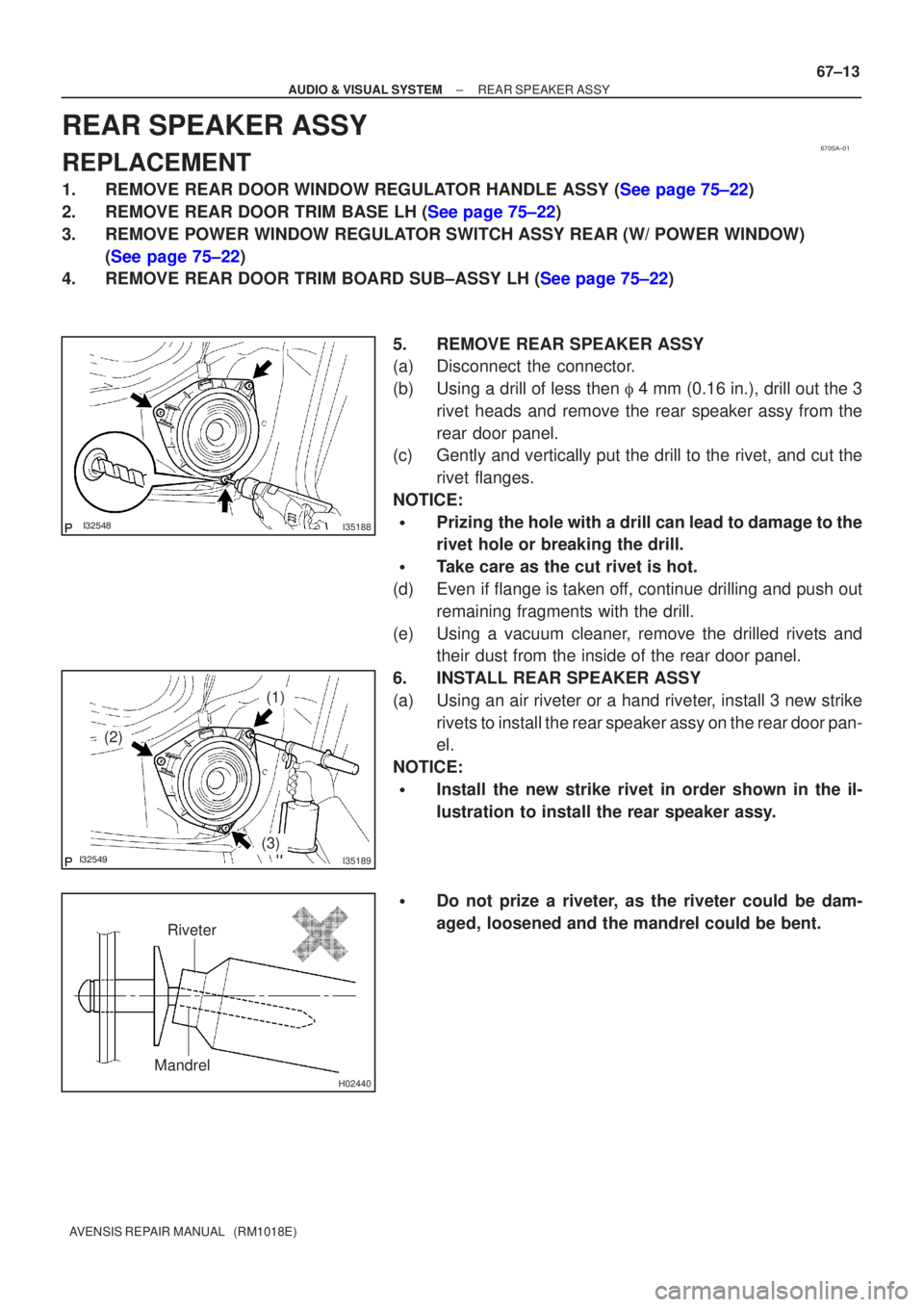
5. REMOVE REAR SPEAKER ASSY
(a) Disconnect the connector.
(b) Using a drill of less then � 4 mm (0.16 in.), drill out the 3
rivet heads and remove the rear speaker assy from the
rear door panel.
(c) Gently and vertically put the drill to the rivet, and cut the
rivet flanges.
NOTICE:
�Prizing the hole with a drill can lead to damage to the
rivet hole or breaking the drill.
�Take care as the cut rivet is hot.
(d) Even if flange is taken off, continue drilling and push out remaining fragments with the drill.
(e) Using a vacuum cleaner, remove the drilled rivets and their dust from the inside of the rear door panel.
6. INSTALL REAR SPEAKER ASSY
(a) Using an air riveter or a hand riveter, install 3 new strike rivets to install the rear speaker assy on the rear door pan-
el.
NOTICE:
�Install the new strike rivet in order shown in the il-
lustration to install the rear speaker assy.
�Do not prize a riveter, as the riveter could be dam-
aged, loosened and the mandrel could be bent.
Page 31 of 1690
H02441
Riveter
Riveter
H02442
Riveter
67±14
± AUDIO & VISUAL SYSTEMREAR SPEAKER ASSY
AVENSIS REPAIR MANUAL (RM1018E)
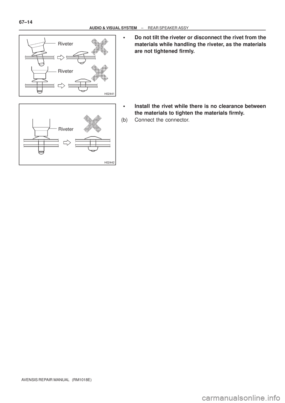
�Do not tilt the riveter or disconnect the rivet from the
materials while handling the riveter, as the materials
are not tightened firmly.
�Install the rivet while there is no clearance between
the materials to tighten the materials firmly.
(b) Connect the connector.
Page 32 of 1690
670SB±01
I36707
±
AUDIO & VISUAL SYSTEM REAR SPEAKER ASSY NO.2
67±15
AVENSIS REPAIR MANUAL (RM1018E)
REAR SPEAKER ASSY NO.2
REPLACEMENT
1. REMOVE REAR DOOR WINDOW REGULATOR HANDLE ASSY (W/O POWER WINDOW)
(See page 75±22)
2. REMOVE POWER WINDOW REGULATOR SWITCH ASSY REAR (W/ POWER WINDOW) (See page 75±22)
3.REMOVE REAR DOOR TRIM BASE LH (See page 75±22)
4.REMOVE REAR DOOR TRIM BOARD SUB±ASSY LH (See page 75±22)
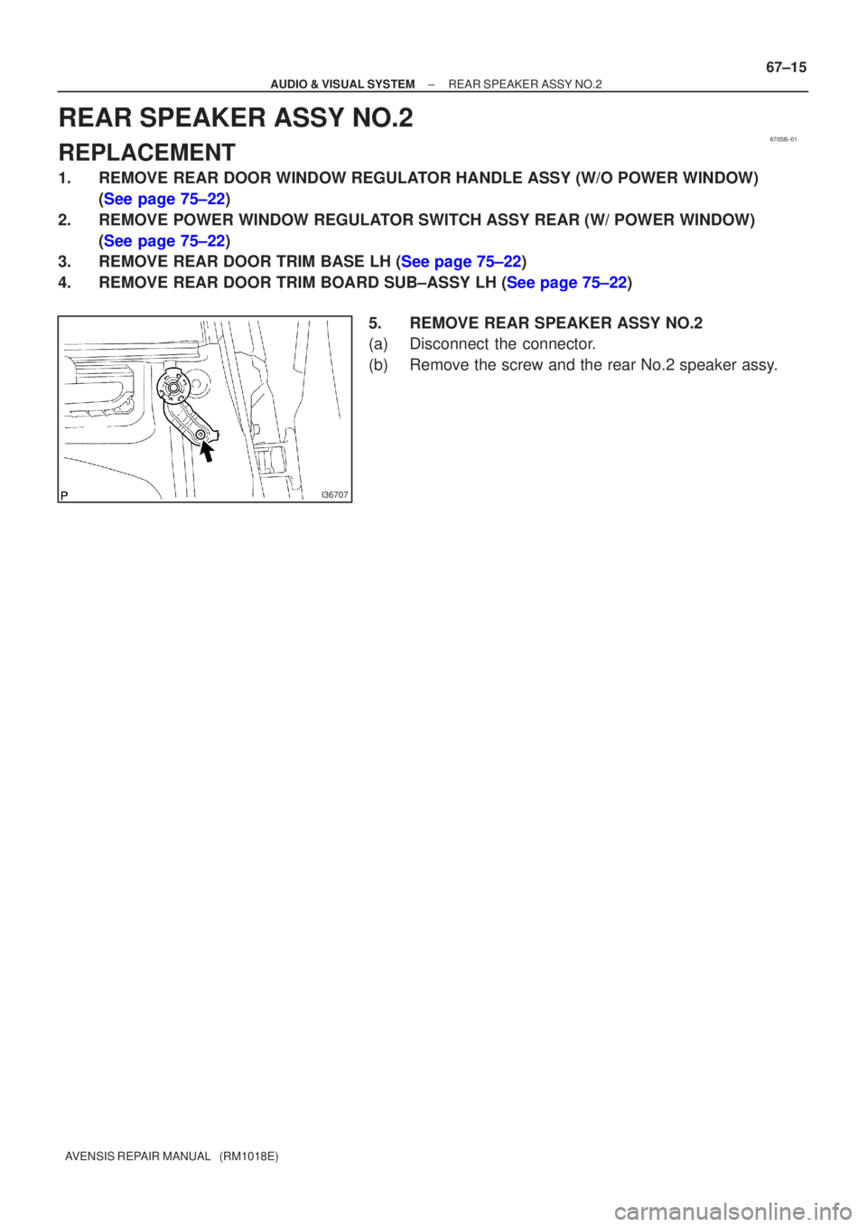
5. REMOVE REAR SPEAKER ASSY NO.2
(a) Disconnect the connector.
(b) Remove the screw and the rear No.2 speaker assy.