Page 188 of 1690
3005C±02
±
DRIVE SHAFT / PROPELLER SHAFT DRIVE SHAFT, PROPELLER SHAFT, AXLE
30±1
AVENSIS REPAIR MANUAL (RM1018E)
DRIVE SHAFT, PROPELLER SHAFT, AXLE
PROBLEM SYMPTOMS TABLE
Use the table below to help you find the cause of the problem. The numbers \
indicate the priority of
the likely cause of the problem. Check each part in order. If necessary, replace these parts.
SymptomSuspect AreaSee page
Wander
5. Wheel
6. Front wheel alignment
7. Rear wheel alignment
8. Hub bearing (Worn)
9. Front shock absorber
10.Rear shock absorber28±1
26±6
27±4
30±2
26±10
27±8
Front wheel shimmy
1. Wheel (Imbalance)
2. Hub bearing (Worn)
3. Lower suspension arm ATM:
4. Lower suspension arm MTM:
5. Lower ball joint (Worm)
6. Front shock absorber28±1
30±2
26±16
26±21
26±24
26±10
Noise (Front)
1. Front drive shaft
2. Front shock absorber
3. Hub bearing (Worn)
4. Lower ball joint (Worm)30±6
26±10 30±2
26±24
Noise (Rear)1. Hub bearing (Worn)
2. Rear shock absorber30±2
27±8
Page 190 of 1690
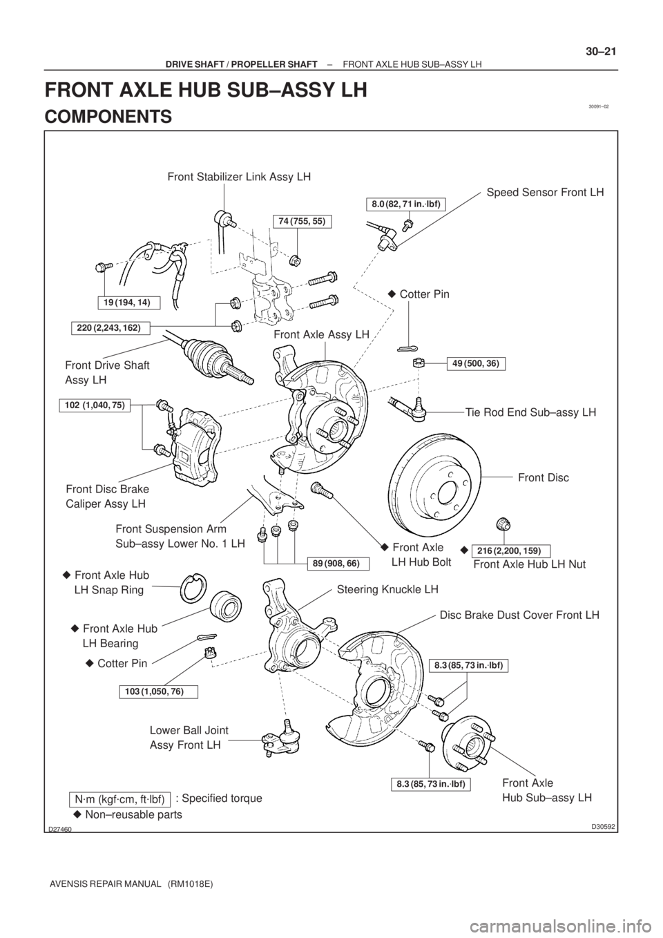
30091±02
������D30592
Speed Sensor Front LH
Lower Ball Joint
Assy Front LH
N�m (kgf�cm, ft�lbf): Specified torque
8.0 (82, 71 in.�lbf)
49 (500, 36)
Tie Rod End Sub±assy LH � Cotter Pin
Front Disc
Front Axle Assy LH
19 (194, 14)
Front Stabilizer Link Assy LH
74 (755, 55)
220 (2,243, 162)
Front Drive Shaft
Assy LH
Front Axle Hub LH Nut
216 (2,200, 159)�� Front Axle
LH Hub Bolt
89 (908, 66)
Steering Knuckle LH
Disc Brake Dust Cover Front LH
8.3 (85, 73 in.�lbf)
8.3 (85, 73 in.�lbf)Front Axle
Hub Sub±assy LH
Front Disc Brake
Caliper Assy LH
Front Suspension Arm
Sub±assy Lower No. 1 LH
� Front Axle Hub
LH Bearing
� Cotter Pin
103 (1,050, 76)
102 (1,040, 75)
� Non±reusable parts � Front Axle Hub
LH Snap Ring
± DRIVE SHAFT / PROPELLER SHAFTFRONT AXLE HUB SUB±ASSY LH
30±21
AVENSIS REPAIR MANUAL (RM1018E)
FRONT AXLE HUB SUB±ASSY LH
COMPONENTS
Page 192 of 1690
F40217
SSTTurn
Hold
C80293
D27403
C83023
± DRIVE SHAFT / PROPELLER SHAFTFRONT AXLE HUB SUB±ASSY LH
30±23
AVENSIS REPAIR MANUAL (RM1018E)
6. REMOVE FRONT DISC
7. SEPARATE TIE ROD END SUB±ASSY LH
(a) Remove the cotter pin and nut.
(b) Using SST, separate the tie rod end sub±assy LH from the
steering knuckle.
SST 09628±62011
8. SEPARATE FRONT SUSPENSION ARM SUB±ASSY
LOWER NO.1 LH
(a) Remove the bolt and 2 nuts, and separate the suspension
arm sub±assy lower No.1 LH from the lower ball joint.
9. REMOVE FRONT AXLE ASSY LH
(a) Using a plastic hammer, separate the drive shaft assy LH
from the axle hub.
NOTICE:
Be careful not to damage the boot and ABS speed sensor
rotor.
(b) Remove the 2 bolts, nuts and steering knuckle with the
shock absorber.
Page 195 of 1690

19.INSTALL LOWER BALL JOINT ASSY FRONT LH
(a)Install the lower ball joint and torque")
C83023
C80293
30±26
±
DRIVE SHAFT / PROPELLER SHAFT FRONT AXLE HUB SUB±ASSY LH
AVENSIS REPAIR MANUAL (RM1018E)
19.INSTALL LOWER BALL JOINT ASSY FRONT LH
(a)Install the lower ball joint and torque the nut. Torque: 103 N �m (1,050 kgf �cm, 76 ft �lbf)
(b)Install a new cotter pin.
NOTICE:
If the holes for the cotter pin are not aligned, tighten the nut up to 6\
0 � further.
20.INSTALL FRONT AXLE ASSY LH
(a)Install the 2 bolts, nuts and steering knuckle with 2 bolts and nuts to the shock absorber.
Torque: 220 N �m (2,243 kgf �cm, 162 ft �lbf)
NOTICE:
Only when reusing the bolts and nuts, apply engine oil to
the screw part of the nuts.
(b)Push the front axle assy toward the outside of the vehicle, fit the splined part of the drive shaft assy to that of the front
axle assy and insert the drive shaft assy into the front axle
assy.
NOTICE:
�Do not push out the front axle assy excessively.
�Be careful not to damage the drive shaft outboard
joint boot.
�Be careful not to damage the speed sensor rotor.
21.INSTALL FRONT SUSPENSION ARM SUB±ASSY LOWER NO.1 LH
(a)Install the front suspension arm sub±assy lower No.1 LH and lower ball joint with the 2 nuts and bolt.
Torque: 89 N �m (908 kgf �cm, 66 ft �lbf)
22.INSTALL TIE ROD END SUB±ASSY LH
(a)Install the tie rod end sub±assy LH to the steering knuckle.
(b)Install the nut and a new cotter pin. Torque: 49 N �m (500 kgf �cm, 36 ft �lbf)
NOTICE:
If the holes for the cotter pin are not aligned, tighten the nut up to 6\
0 � further.
23.INSTALL FRONT STABILIZER LINK ASSY LH (See page 30±6)
24. INSTALL FRONT DISC
Page 199 of 1690
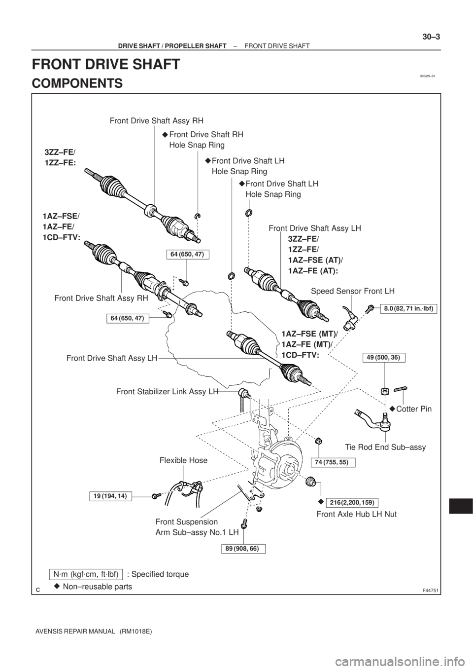
300JW±01
F44751
N�m (kgf�cm, ft�lbf) : Specified torque
Non±reusable parts �Front Suspension
Arm Sub±assy No.1 LH
89 (908, 66)
19 (194, 14)
74 (755, 55)
64 (650, 47)
49 (500, 36)
216 (2,200, 159)�
Front Axle Hub LH Nut Flexible Hose
Tie Rod End Sub±assy�Cotter Pin �Front Drive Shaft RH
Hole Snap Ring Front Drive Shaft Assy RH
Front Drive Shaft Assy RH 1AZ±FSE/
1AZ±FE/
1CD±FTV:
Speed Sensor Front LH
8.0 (82, 71 in.�lbf)
Front Drive Shaft Assy LH
Front Stabilizer Link Assy LH
3ZZ±FE/
1ZZ±FE:
64 (650, 47)
Front Drive Shaft Assy LH
3ZZ±FE/
1ZZ±FE/
1AZ±FSE (AT)/
1AZ±FE (AT):
1AZ±FSE (MT)/
1AZ±FE (MT)/
1CD±FTV:
�Front Drive Shaft LH
Hole Snap Ring
�Front Drive Shaft LH
Hole Snap Ring
± DRIVE SHAFT / PROPELLER SHAFTFRONT DRIVE SHAFT
30±3
AVENSIS REPAIR MANUAL (RM1018E)
FRONT DRIVE SHAFT
COMPONENTS
Page 204 of 1690
������F45753HoldTurn
SST
G21537
G21542
G20965
30±32
± DRIVE SHAFT / PROPELLER SHAFTREAR AXLE CARRIER SUB±ASSY LH
AVENSIS REPAIR MANUAL (RM1018E)
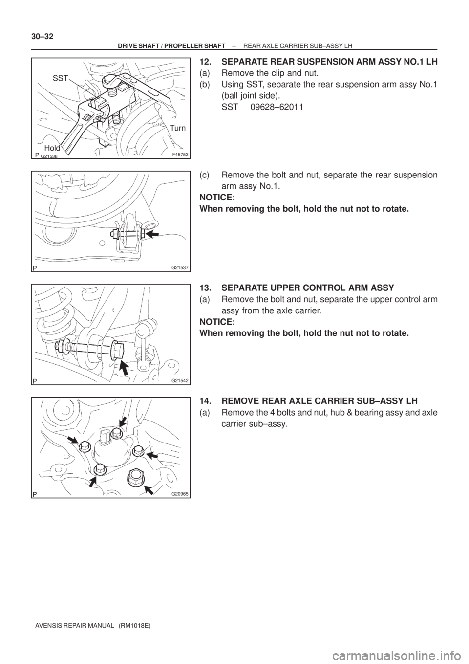
12. SEPARATE REAR SUSPENSION ARM ASSY NO.1 LH
(a) Remove the clip and nut.
(b) Using SST, separate the rear suspension arm assy No.1
(ball joint side).
SST 09628±62011
(c) Remove the bolt and nut, separate the rear suspension
arm assy No.1.
NOTICE:
When removing the bolt, hold the nut not to rotate.
13. SEPARATE UPPER CONTROL ARM ASSY
(a) Remove the bolt and nut, separate the upper control arm
assy from the axle carrier.
NOTICE:
When removing the bolt, hold the nut not to rotate.
14. REMOVE REAR AXLE CARRIER SUB±ASSY LH
(a) Remove the 4 bolts and nut, hub & bearing assy and axle
carrier sub±assy.
Page 205 of 1690

15. INSPECT REAR AXLE CARRIER SUB±ASSY LH
(a) As shown in the illus")
G21613
G20965
G21542
G21537
± DRIVE SHAFT / PROPELLER SHAFTREAR AXLE CARRIER SUB±ASSY LH
30±33
AVENSIS REPAIR MANUAL (RM1018E)
15. INSPECT REAR AXLE CARRIER SUB±ASSY LH
(a) As shown in the illustration, flip the ball joint stud back and
forth 5 times, before installing the nut.
(b) Using a torque wrench, turn the nut continuously at a rate
of 3 ± 5 seconds per turn and take the torque reading on
the 5th turn.
Turning torque (Maximum):
3.0 N�m (30 kgf�cm, 27 in.�lbf)
NOTICE:
�Neither abnormal drag nor rattle exists during the
rotation.
�Neither crack nor grease leakage exists and deforma-
tion on the dust cover.
16. INSTALL REAR AXLE CARRIER SUB±ASSY LH
(a) Install the hub & bearing assy and rear axle carrier sub±
assy with the 4 bolts and nut.
Torque:
Bolt: 56 N�m (571 kgf�cm, 41 ft�lbf)
Nut: 140 N�m (1,428 kgf�cm, 103 ft�lbf)
17. TEMPORARILY TIGHTEN UPPER CONTROL ARM
ASSY
(a) Temporarily tighten the upper control arm assy with the
bolt and nut.
Temporarily tighten torque:
7 ± 13 N�m (71 ± 133 kgf�cm, 5.1 ± 9.6 ft�lbf)
HINT:
Insert the bolt from the rear side of the vehicle and temporarily
install the bolt.
18. TEMPORARILY TIGHTEN REAR SUSPENSION ARM
ASSY NO.1 LH
(a) Temporarily tighten the rear suspension arm assy (ball
joint side) with the nut.
(b) Temporarily tighten the bolt and nut.
Temporarily tighten torque:
7 ± 13 N�m (71 ± 133 kgf�cm, 5.1 ± 9.6 ft�lbf)
HINT:
Insert the bolt from the rear side of the vehicle and temporarily
install the bolt.
Page 206 of 1690

19.TEMPORARILY TIGHTEN LOWER CONTROL ARM ASSY LH
(a)Temporarily tigh")
G21543
F44820
������F45267
30±34
±
DRIVE SHAFT / PROPELLER SHAFT REAR AXLE CARRIER SUB±ASSY LH
AVENSIS REPAIR MANUAL (RM1018E)
19.TEMPORARILY TIGHTEN LOWER CONTROL ARM ASSY LH
(a)Temporarily tighten the lower control arm assy with the
nut.
Temporarily tighten Torque:
7 ± 13 N �m (71 ± 133 kgf �cm, 5.1 ± 9.6 ft �lbf)
20.CONNECT PARKING BRAKE CABLE ASSY NO.3
(a)Connect the parking brake cable assy No.3 to the backing plate.
21.INSTALL PARKING BRAKE SHOE LEVER LH (See page 33±14)
22.INSTALL PARKING BRAKE SHOE KIT (See page 33±14) SST 09718±00010
23.INSTALL PARKING BRAKE SHOE ADJUSTING SCREW SET (See page 33±14)
24.INSTALL PARKING BRAKE ADJUSTER KIT (See page 33±14)
25.CHECK PARKING BRAKE INSTALLATION (See page 33±14)
26.INSPECT BEARING BACKLASH (See page 30±2)
27.INSPECT AXLE HUB DEVIATION (See page 30±2)
28. INSTALL REAR DISC
29.ADJUST PARKING BRAKE SHOE CLEARANCE (See page 33±14)
30. INSTALL REAR DISC BRAKE CALIPER ASSY LH
(a) Install the rear disc brake caliper with the 2 bolts. Torque: 47 N �m (475 kgf �cm, 34 ft �lbf)
31. CONNECT SKID CONTROL SENSOR WIRE
(a) Connect the skid control sensor wire with the bolt. Torque: 5.0 N �m (51 kgf �cm, 44 in. �lbf)
(b) Connect the connector.
HINT:
Do not twist the sensor wire when installing the sensor.
32. INSTALL REAR WHEEL Torque: 103 N �m (1,050 kgf �cm, 76 ft �lbf)
33.STABILIZE SUSPENSION (See page 27±8)

DRIVE SHAFT, PROPELLER SHAFT, AXLE
PROBLEM SYMPTOMS TABLE
Use the table below to h")

6. REMOVE FRONT DISC
7. SEPARATE TIE ROD END SUB±ASSY LH")