Page 567 of 1690
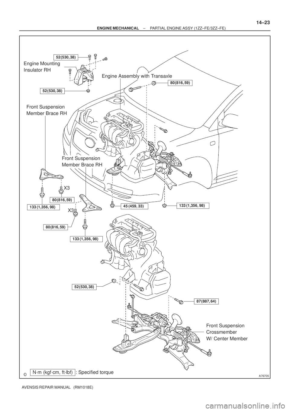
A76705N´m (kgf´cm, ft´lbf) : Specified torque Engine Mounting
Insulator RH
Engine Assembly with Transaxle
Front Suspension
Crossmember
W/ Center Member
80 (816, 59)
133 (1,356, 98)45 (459, 33)
52 (530, 38)
52 (530, 38)
87 (887, 64)
52 (530, 38)
Front Suspension
Member Brace RH
133 (1,356, 98)
80 (816, 59)
Front Suspension
Member Brace RH
133 (1,356, 98)
80 (816, 59)
X3
X3
± ENGINE MECHANICALPARTIAL ENGINE ASSY (1ZZ±FE/3ZZ±FE)
14±23
AVENSIS REPAIR MANUAL (RM1018E)
Page 575 of 1690
A64005
±
ENGINE MECHANICAL PARTIAL ENGINE ASSY (1ZZ±FE/3ZZ±FE)
14±31
AVENSIS REPAIR MANUAL (RM1018E)
40.REMOVE GENERATOR ASSY (See page 19±7)
41. SEPARATE COMPRESSOR AND MAGNETIC CLUTCH (W/ AIR CONDITIONING)
HINT:
�Secure the compressor and hoses off to the side instead of discharging the A/C system.
�1ZZ±FE (See page 55±74)
�3ZZ±FE (See page 55±70)
42. REMOVE COLUMN HOLE COVER SILENCER SHEET
(a) Remove the 2 clips and the column hole cover silencer sheet.
43.SEPARATE STEERING INTERMEDIATE SHAFT (See page 50±9)
44.REMOVE FRONT DOOR SCUFF PLATE RH (See page 71±11)
45.REMOVE COWL SIDE TRIM BOARD RH (See page 71±11)
46. REMOVE FRONT FLOOR FOOTREST
47. REMOVE FLOOR PANEL BRACE FRONT
(a) Remove the 2 nuts and the floor panel brace front.
48.REMOVE EXHAUST PIPE ASSY FRONT (See page 15±2)
49.REMOVE FRONT AXLE HUB LH NUT (See page 30±6)
SST 09930±00010
50. REMOVE FRONT AXLE HUB RH NUT SST 09930±00010
HINT:
Perform the same procedure as above on the opposite side.
51.SEPARATE TIE ROD END SUB±ASSY LH (See page 30±6)
SST 09628±62011
52. SEPARATE TIE ROD END SUB±ASSY RH SST 09628±62011
HINT:
Perform the same procedure as above on the opposite side.
53.SEPARATE FRONT STABILIZER LINK ASSY LH (See page 30±6)
54. SEPARATE FRONT STABILIZER LINK ASSY RH
HINT:
Perform the same procedure as above on the opposite side.
55.SEPARATE FRONT SUSPENSION ARM SUB±ASSY LOWER NO.1 LH (See page 30±6)
56. SEPARATE FRONT SUSPENSION ARM SUB±ASSY LOWER NO.1 RH
HINT:
Perform the same procedure as above on the opposite side.
57.SEPARATE FRONT AXLE ASSY LH (See page 30±6)
58. SEPARATE FRONT AXLE ASSY RH
HINT:
Perform the same procedure as above on the opposite side.
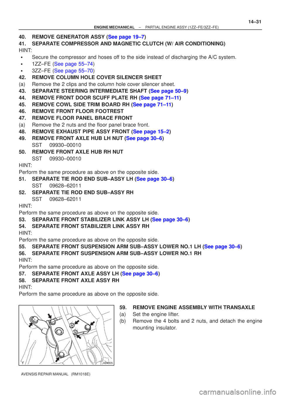
59. REMOVE ENGINE ASSEMBLY WITH TRANSAXLE
(a) Set the engine lifter.
(b) Remove the 4 bolts and 2 nuts, and detach the enginemounting insulator.
Page 576 of 1690
A76715
A76717
A76716
A62830Front SideRear Side 14±32
± ENGINE MECHANICALPARTIAL ENGINE ASSY (1ZZ±FE/3ZZ±FE)
AVENSIS REPAIR MANUAL (RM1018E)
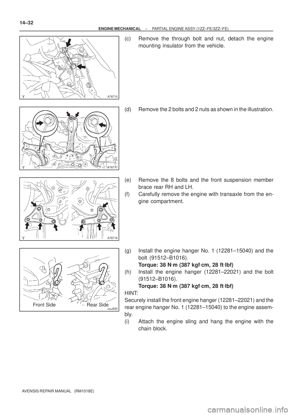
(c) Remove the through bolt and nut, detach the engine
mounting insulator from the vehicle.
(d) Remove the 2 bolts and 2 nuts as shown in the illustration.
(e) Remove the 8 bolts and the front suspension member
brace rear RH and LH.
(f) Carefully remove the engine with transaxle from the en-
gine compartment.
(g) Install the engine hanger No. 1 (12281±15040) and the
bolt (91512±B1016).
Torque: 38 N�m (387 kgf�cm, 28 ft�lbf)
(h) Install the engine hanger (12281±22021) and the bolt
(91512±B1016).
Torque: 38 N�m (387 kgf�cm, 28 ft�lbf)
HINT:
Securely install the front engine hanger (12281±22021) and the
rear engine hanger No. 1 (12281±15040) to the engine assem-
bly.
(i) Attach the engine sling and hang the engine with the
chain block.
Page 577 of 1690
A76718
A76719
A62838SST
A62838SST
±
ENGINE MECHANICAL PARTIAL ENGINE ASSY (1ZZ±FE/3ZZ±FE)
14±33
AVENSIS REPAIR MANUAL (RM1018E)
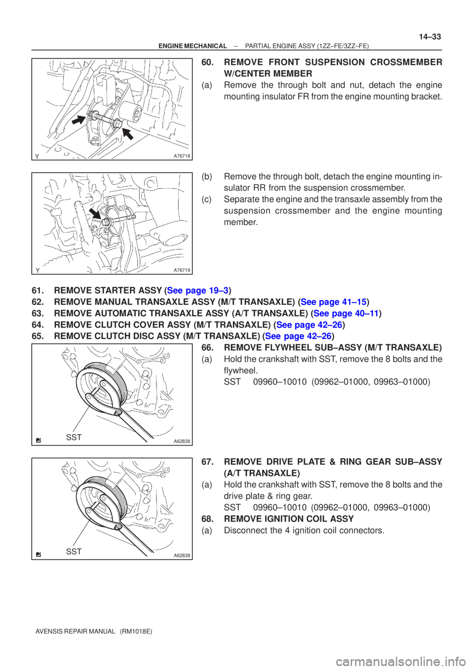
60. REMOVE FRONT SUSPENSION CROSSMEMBER
W/CENTER MEMBER
(a) Remove the through bolt and nut, detach the engine
mounting insulator FR from the engine mounting bracket.
(b) Remove the through bolt, detach the engine mounting in- sulator RR from the suspension crossmember.
(c) Separate the engine and the transaxle assembly from the suspension crossmember and the engine mounting
member.
61.REMOVE STARTER ASSY(See page 19±3)
62.REMOVE MANUAL TRANSAXLE ASSY (M/T TRANSAXLE) (See page 41±15)
63.REMOVE AUTOMATIC TRANSAXLE ASSY (A/T TRANSAXLE) (See page 40±11)
64.REMOVE CLUTCH COVER ASSY (M/T TRANSAXLE) (See page 42±26)
65.REMOVE CLUTCH DISC ASSY (M/T TRANSAXLE)(See page 42±26) 66. REMOVE FLYWHEEL SUB±ASSY (M/T TRANSAXLE)
(a) Hold the crankshaft with SST, remove the 8 bolts and theflywheel.
SST 09960±10010 (09962±01000, 09963±01000)
67. REMOVE DRIVE PLATE & RING GEAR SUB±ASSY (A/T TRANSAXLE)
(a) Hold the crankshaft with SST, remove the 8 bolts and the
drive plate & ring gear.
SST 09960±10010 (09962±01000, 09963±01000)
68. REMOVE IGNITION COIL ASSY
(a) Disconnect the 4 ignition coil connectors.
Page 586 of 1690
A62204
1
5
3
82
6
4
7
A76719
A76718
A76717
14±42
±
ENGINE MECHANICAL PARTIAL ENGINE ASSY (1ZZ±FE/3ZZ±FE)
AVENSIS REPAIR MANUAL (RM1018E)
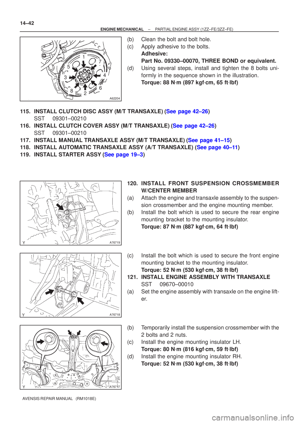
(b) Clean the bolt and bolt hole.
(c) Apply adhesive to the bolts. Adhesive:
Part No. 09330±00070, THREE BOND or equivalent.
(d) Using several steps, install and tighten the 8 bolts uni- formly in the sequence shown in the illustration.
Torque: 88 N �m (897 kgf �cm, 65 ft �lbf)
115.INSTALL CLUTCH DISC ASSY (M/T TRANSAXLE)(See page 42±26) SST 09301±00210
116.INSTALL CLUTCH COVER ASSY (M/T TRANSAXLE)(See page 42±26) SST 09301±00210
117.INSTALL MANUAL TRANSAXLE ASSY (M/T TRANSAXLE)(See page 41±15)
118.INSTALL AUTOMATIC TRANSAXLE ASSY (A/T TRANSAXLE) (See page 40±11)
119.INSTALL STARTER ASSY(See page 19±3)
120. INS TALL FRO NT SUSPENSION CROSSMEMBER
W/CENTER MEMBER
(a) Attach the engine and transaxle assembly to the suspen- sion crossmember and the engine mounting member.
(b) Install the bolt which is used to secure the rear engine
mounting bracket to the mounting insulator.
Torque: 87 N �m (887 kgf �cm, 64 ft �lbf)
(c) Install the bolt which is used to secure the front engine mounting bracket to the mounting insulator.
Torque: 52 N �m (530 kgf �cm, 38 ft �lbf)
121. INSTALL ENGINE ASSEMBLY WITH TRANSAXLE
SST 09670±00010
(a) Set the engine assembly with transaxle on the engine lift- er.
(b) Temporarily install the suspension crossmember with the 2 bolts and 2 nuts.
(c) Install the engine mounting insulator LH.
Torque: 80 N �m (816 kgf �cm, 59 ft �lbf)
(d) Install the engine mounting insulator RH. Torque: 52 N �m (530 kgf �cm, 38 ft �lbf)
Page 587 of 1690
A76717
A
B
A
B
A76716
AA
BBBBBB
±
ENGINE MECHANICAL PARTIAL ENGINE ASSY (1ZZ±FE/3ZZ±FE)
14±43
AVENSIS REPAIR MANUAL (RM1018E)
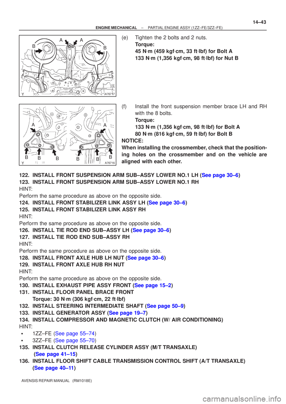
(e) Tighten the 2 bolts and 2 nuts.
Torque:
45 N�m (459 kgf �cm, 33 ft �lbf) for Bolt A
133 N �m (1,356 kgf �cm, 98 ft �lbf) for Nut B
(f) Install the front suspension member brace LH and RH with the 8 bolts.
Torque:
133 N �m (1,356 kgf �cm, 98 ft �lbf) for Bolt A
80 N �m (816 kgf �cm, 59 ft �lbf) for Bolt B
NOTICE:
When installing the crossmember, check that the position-
ing holes on the crossmember and on the vehicle are
aligned with each other.
122.INSTALL FRONT SUSPENSION ARM SUB±ASSY LOWER NO.1 LH (See page 30±6)
123. INSTALL FRONT SUSPENSION ARM SUB±ASSY LOWER NO.1 RH
HINT:
Perform the same procedure as above on the opposite side.
124.INSTALL FRONT STABILIZER LINK ASSY LH (See page 30±6)
125. INSTALL FRONT STABILIZER LINK ASSY RH
HINT:
Perform the same procedure as above on the opposite side.
126.INSTALL TIE ROD END SUB±ASSY LH (See page 30±6)
127. INSTALL TIE ROD END SUB±ASSY RH
HINT:
Perform the same procedure as above on the opposite side.
128.INSTALL FRONT AXLE HUB LH NUT (See page 30±6)
129. INSTALL FRONT AXLE HUB RH NUT
HINT:
Perform the same procedure as above on the opposite side.
130.INSTALL EXHAUST PIPE ASSY FRONT (See page 15±2)
131. INSTALL FLOOR PANEL BRACE FRONT Torque: 30 N �m (306 kgf �cm, 22 ft �lbf)
132.INSTALL STEERING INTERMEDIATE SHAFT (See page 50±9)
133.INSTALL GENERATOR ASSY (See page 19±7)
134. INSTALL COMPRESSOR AND MAGNETIC CLUTCH (W/ AIR CONDITIONING)
HINT:
�1ZZ±FE (See page 55±74)
�3ZZ±FE (See page 55±70)
135. INSTALL CLUTCH RELEASE CYLINDER ASSY (M/T TRANSAXLE) (See page 41±15)
136. INSTALL FLOOR SHIFT CABLE TRANSMISSION CONTROL SHIFT (A/T TRANSAXLE) (See page 40±11)
Page 694 of 1690
2600M±04
F13686
C80880
F13683
F44622
26±10
±
FRONT SUSPENSION FRONT SHOCK ABSORBER WITH COIL SPRING
AVENSIS REPAIR MANUAL (RM1018E)
FRONT SHOCK ABSORBER WITH COIL SPRING
OVERHAUL
HINT:
�COMPONENTS: See page 26±2
�This procedure is provided for the overhaul on the LH side. Overhaul the oth\
er side by the same proce-
dure as the LH side.
1. REMOVE FRONT WHEEL
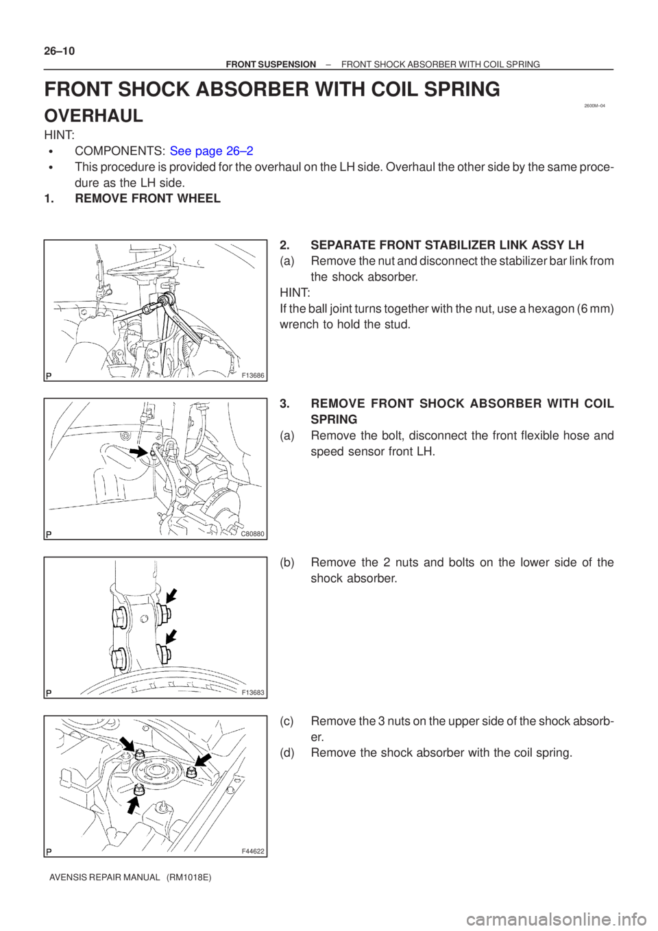
2. SEPARATE FRONT STABILIZER LINK ASSY LH
(a) Remove the nut and disconnect the stabilizer bar link fromthe shock absorber.
HINT:
If the ball joint turns together with the nut, use a hexagon (6 mm)
wrench to hold the stud.
3. REMOVE FRONT SHOCK ABSORBER WITH COIL SPRING
(a) Remove the bolt, disconnect the front flexible hose and speed sensor front LH.
(b) Remove the 2 nuts and bolts on the lower side of the shock absorber.
(c) Remove the 3 nuts on the upper side of the shock absorb- er.
(d) Remove the shock absorber with the coil spring.
Page 695 of 1690
28mm
F44963
F40270
SST
F08624
SST
± FRONT SUSPENSIONFRONT SHOCK ABSORBER WITH COIL SPRING
26±11
AVENSIS REPAIR MANUAL (RM1018E)
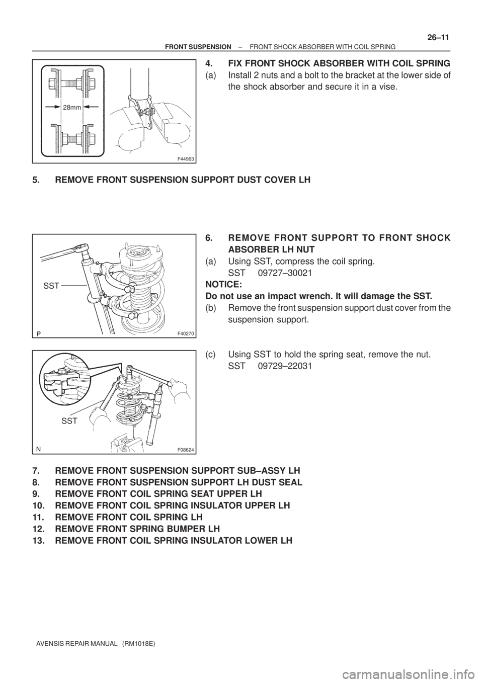
4. FIX FRONT SHOCK ABSORBER WITH COIL SPRING
(a) Install 2 nuts and a bolt to the bracket at the lower side of
the shock absorber and secure it in a vise.
5. REMOVE FRONT SUSPENSION SUPPORT DUST COVER LH
6. REMOVE FRONT SUPPORT TO FRONT SHOCK
ABSORBER LH NUT
(a) Using SST, compress the coil spring.
SST 09727±30021
NOTICE:
Do not use an impact wrench. It will damage the SST.
(b) Remove the front suspension support dust cover from the
suspension support.
(c) Using SST to hold the spring seat, remove the nut.
SST 09729±22031
7. REMOVE FRONT SUSPENSION SUPPORT SUB±ASSY LH
8. REMOVE FRONT SUSPENSION SUPPORT LH DUST SEAL
9. REMOVE FRONT COIL SPRING SEAT UPPER LH
10. REMOVE FRONT COIL SPRING INSULATOR UPPER LH
11. REMOVE FRONT COIL SPRING LH
12. REMOVE FRONT SPRING BUMPER LH
13. REMOVE FRONT COIL SPRING INSULATOR LOWER LH