Page 712 of 1690
2600K±06
±
FRONT SUSPENSION FRONT SUSPENSION SYSTEM
26±1
AVENSIS REPAIR MANUAL (RM1018E)
FRONT SUSPENSION SYSTEM
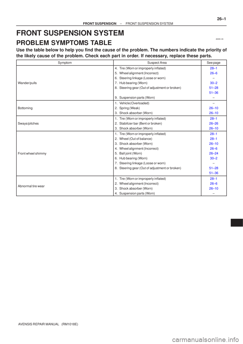
PROBLEM SYMPTOMS TABLE
Use the table below to help you find the cause of the problem. The numbers \
indicate the priority of
the likely cause of the problem. Check each part in order. If necessary, replace these parts.
SymptomSuspect AreaSee page
Wander/pulls
4. Tire (Worn or improperly inflated)
5. Wheel alignment (Incorrect)
6. Steering linkage (Loose or worn)
7. Hub bearing (Worn)
8. Steering gear (Out of adjustment or broken)
9. Suspension parts (Worn)28±1
26±6
±
30±2
51±28
51±36
±
Bottoming
1. Vehicle (Overloaded)
2. Spring (Weak)
3. Shock absorber (Worn)±
26±10
26±10
Sways/pitches
1. Tire (Worn or improperly inflated)
2. Stabilizer bar (Bent or broken)
3. Shock absorber (Worn)28±1
26±26
26±10
Front wheel shimmy
1. Tire (Worn or improperly inflated)
2. Wheel (Out of balance)
3. Shock absorber (Worn)
4. Wheel alignment (Incorrect)
5. Ball joint (Worn)
6. Hub bearing (Worn)
7. Steering linkage (Loose or worn)
8. Steering gear (Out of adjustment or broken)28±1
28±1
26±10 26±6
26±24
30±2 ±
51±28
51±36
Abnormal tire wear
1. Tire (Worn or improperly inflated)
2. Wheel alignment (Incorrect)
3. Shock absorber (Worn)
4. Suspension parts (Worn)28±1
26±6
26±10 ±
Page 948 of 1690
710CN±02
I34628
C10±19
C10±5
± INSTRUMENT PANEL/METERCOMBINATION METER
71±3
AVENSIS REPAIR MANUAL (RM1018E)
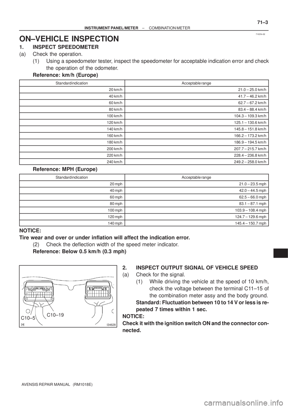
ON±VEHICLE INSPECTION
1. INSPECT SPEEDOMETER
(a) Check the operation.
(1) Using a speedometer tester, inspect the speedometer for acceptable indication error and check
the operation of the odometer.
Reference: km/h (Europe)
Standard indicationAcceptable range
20 km/h21.0 ± 25.0 km/h
40 km/h41.7 ± 46.2 km/h
60 km/h62.7 ± 67.2 km/h
80 km/h83.4 ± 88.4 km/h
100 km/h104.3 ± 109.3 km/h
120 km/h125.1 ± 130.6 km/h
140 km/h145.8 ± 151.8 km/h
160 km/h166.2 ± 173.2 km/h
180 km/h186.9 ± 194.5 km/h
200 km/h207.7 ± 215.7 km/h
220 km/h228.4 ± 236.8 km/h
240 km/h249.2 ± 258.0 km/h
Reference: MPH (Europe)
Standard indicationAcceptable range
20 mph21.0 ± 23.5 mph
40 mph42.0 ± 44.5 mph
60 mph62.5 ± 66.0 mph
80 mph83.1 ± 87.1 mph
100 mph103.9 ± 108.4 mph
120 mph124.7 ± 129.6 mph
140 mph145.4 ± 150.7 mph
NOTICE:
Tire wear and over or under inflation will affect the indication error.
(2) Check the deflection width of the speed meter indicator.
Reference: Below 0.5 km/h (0.3 mph)
2. INSPECT OUTPUT SIGNAL OF VEHICLE SPEED
(a) Check for the signal.
(1) While driving the vehicle at the speed of 10 km/h,
check the voltage between the terminal C11±15 of
the combination meter assy and the body ground.
Standard: Fluctuation between 10 to 14 V or less is re-
peated 7 times within 1 sec.
NOTICE:
Check it with the ignition switch ON and the connector con-
nected.
Page 1011 of 1690
010B5±11
D25082
Rubber Attachment
D27697
: SUPPORT POSITION, PAN
TOGRAPH JACK POSITION
: CENTER OF VEHICLE GRAVITY
(unload condition)
: JACK POSITION
± INTRODUCTIONREPAIR INSTRUCTION
01±19
AVENSIS REPAIR MANUAL (RM1018E)
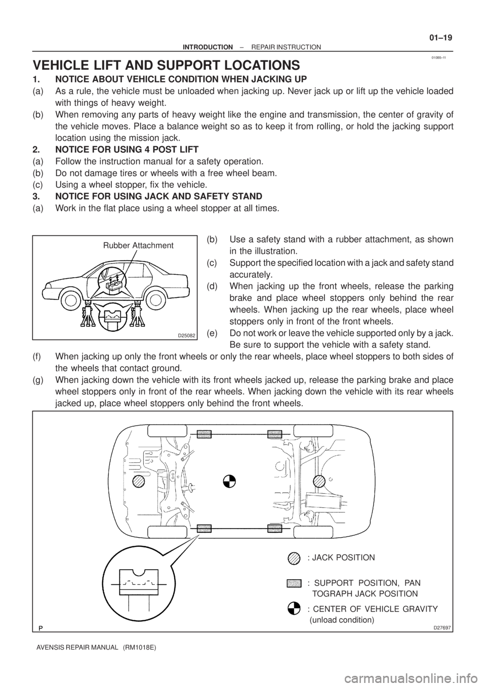
VEHICLE LIFT AND SUPPORT LOCATIONS
1. NOTICE ABOUT VEHICLE CONDITION WHEN JACKING UP
(a) As a rule, the vehicle must be unloaded when jacking up. Never jack up or lift up the vehicle loaded
with things of heavy weight.
(b) When removing any parts of heavy weight like the engine and transmission, the center of gravity of
the vehicle moves. Place a balance weight so as to keep it from rolling, or hold the jacking support
location using the mission jack.
2. NOTICE FOR USING 4 POST LIFT
(a) Follow the instruction manual for a safety operation.
(b) Do not damage tires or wheels with a free wheel beam.
(c) Using a wheel stopper, fix the vehicle.
3. NOTICE FOR USING JACK AND SAFETY STAND
(a) Work in the flat place using a wheel stopper at all times.
(b) Use a safety stand with a rubber attachment, as shown
in the illustration.
(c) Support the specified location with a jack and safety stand
accurately.
(d) When jacking up the front wheels, release the parking
brake and place wheel stoppers only behind the rear
wheels. When jacking up the rear wheels, place wheel
stoppers only in front of the front wheels.
(e) Do not work or leave the vehicle supported only by a jack.
Be sure to support the vehicle with a safety stand.
(f) When jacking up only the front wheels or only the rear wheels, place wheel stoppers to both sides of
the wheels that contact ground.
(g) When jacking down the vehicle with its front wheels jacked up, release the parking brake and place
wheel stoppers only in front of the rear wheels. When jacking down the vehicle with its rear wheels
jacked up, place wheel stoppers only behind the front wheels.
Page 1023 of 1690
650SY±01
I35230
±
LIGHTING FOG LAMP ASSY LH
65±23
AVENSIS REPAIR MANUAL (RM1018E)
ADJUSTMENT
1.PUT VEHICLE THESE CONDITIONS
(a)Tire inflation pressure is within the specified value. (See page 28±1)
(b) Start the engine.
2. ADJUST FOG LIGHT AIM
(a) The fog light aim can be adjusted by turning the aimingscrew in the vertical direction.
HINT:
The optical aim moves upward when turning the screwdriver
clockwise and moves downward when turning the screwdriver
center clockwise.
3. CHECK FOG LIGHT AIM
Page 1030 of 1690
650SV±01
I33423
V LH LineV RH LineV Line
Ground
H Line
± LIGHTINGHEADLAMP UNIT LH
65±19
AVENSIS REPAIR MANUAL (RM1018E)
ADJUSTMENT
1. HEADLIGHT AIM ONLY
HINT:
�Perform aiming adjustment with Low±beam.
�Since the Low±beam light and the High±beam light is a
unit, if aiming on either side is connect, the other side
should also be connect.
However, check both beams just to make sure.
(a) Prepare vehicle in the following conditions.
�Check that any damage or deformation does not exist on
the body around the headlights.
�Fuel tank is full.
�The tire inflation pressure is at the specified level.
�Vehicle is parked at a level surface.
�A person having an average weight sits in the driver's
seat.
�Vehicle is bounced up and down to stabilize the suspen-
sion to the normal position.
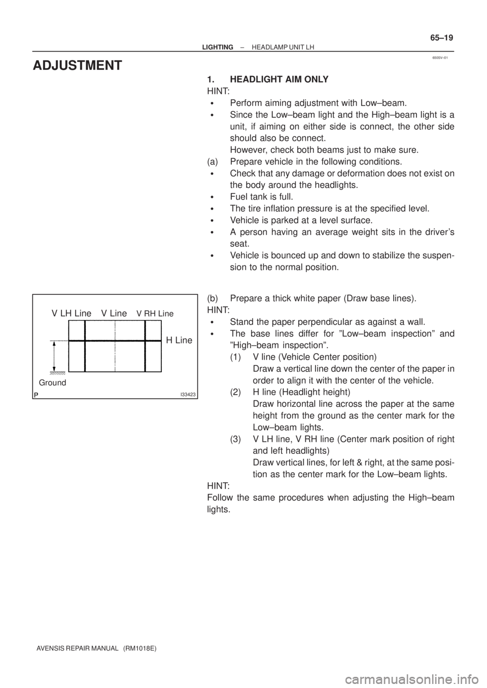
(b) Prepare a thick white paper (Draw base lines).
HINT:
�Stand the paper perpendicular as against a wall.
�The base lines differ for ºLow±beam inspectionº and
ºHigh±beam inspectionº.
(1) V line (Vehicle Center position)
Draw a vertical line down the center of the paper in
order to align it with the center of the vehicle.
(2) H line (Headlight height)
Draw horizontal line across the paper at the same
height from the ground as the center mark for the
Low±beam lights.
(3) V LH line, V RH line (Center mark position of right
and left headlights)
Draw vertical lines, for left & right, at the same posi-
tion as the center mark for the Low±beam lights.
HINT:
Follow the same procedures when adjusting the High±beam
lights.
Page 1136 of 1690
5100G±06
51±2
±
POWER STEERING POWER STEERING SYSTEM
AVENSIS REPAIR MANUAL (RM1018E)
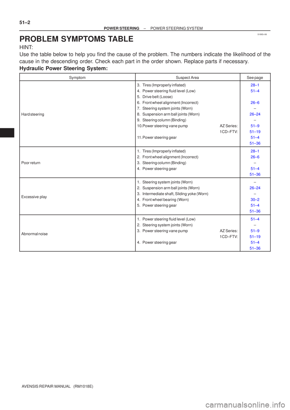
PROBLEM SYMPTOMS TABLE
HINT:
Use the table below to help you find the cause of the problem. The numbers \
indicate the likelihood of the
cause in the descending order. Check each part in the order shown. Replace parts if necessary.
Hydraulic Power Steering System:
SymptomSuspect AreaSee page
Hard steering
3. Tires (Improperly inflated)
4. Power steering fluid level (Low)
5. Drive belt (Loose)
6. Front wheel alignment (Incorrect)
7. Steering system joints (Worn)
8. Suspension arm ball joints (Worn)
9. Steering column (Binding)
10.Power steering vane pump AZ Series: 1CD±FTV:
11. Power steering gear28±1
51±4
26±6 ±
26±24 ±
51±9
51±19 51±4
51±36
Poor return
1. Tires (Improperly inflated)
2. Front wheel alignment (Incorrect)
3. Steering column (Binding)
4. Power steering gear28±1
26±6 ±
51±4
51±36
Excessive play
1. Steering system joints (Worn)
2. Suspension arm ball joints (Worn)
3. Intermediate shaft, Sliding yoke (Worn)
4. Front wheel bearing (Worn)
5. Power steering gear±
26±24 ±
30±2
51±4
51±36
Abnormal noise
1. Power steering fluid level (Low)
2. Steering system joints (Worn)
3. Power steering vane pump AZ Series: 1CD±FTV:
4. Power steering gear51±4
±
51±9
51±19 51±4
51±36
Page 1137 of 1690
±
POWER STEERING POWER STEERING SYSTEM
51±3
AVENSIS REPAIR MANUAL (RM1018E)
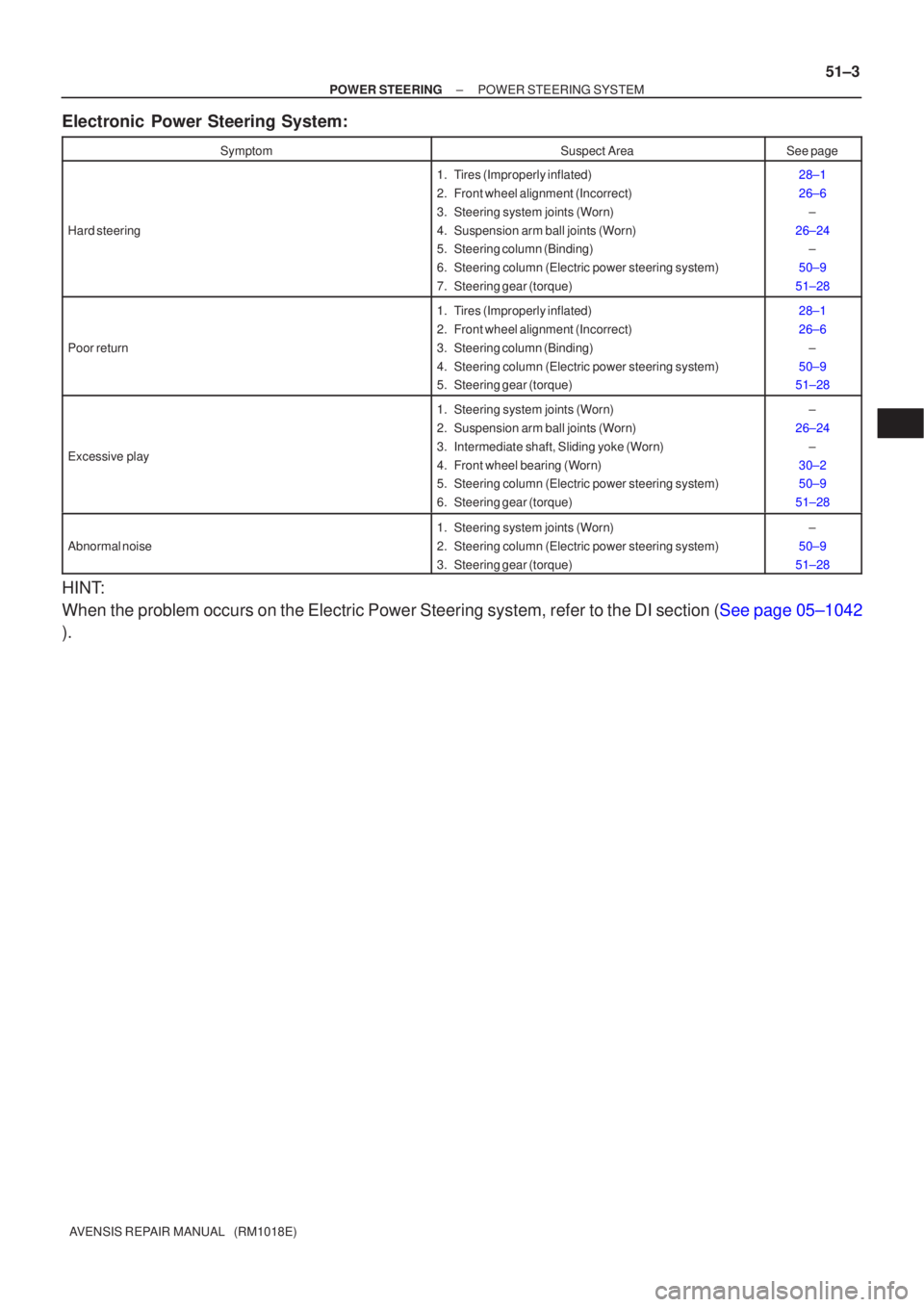
Electronic Power Steering System:
SymptomSuspect AreaSee page
Hard steering
1. Tires (Improperly inflated)
2. Front wheel alignment (Incorrect)
3. Steering system joints (Worn)
4. Suspension arm ball joints (Worn)
5. Steering column (Binding)
6. Steering column (Electric power steering system)
7. Steering gear (torque)28±1
26±6
±
26±24 ±
50±9
51±28
Poor return
1. Tires (Improperly inflated)
2. Front wheel alignment (Incorrect)
3. Steering column (Binding)
4. Steering column (Electric power steering system)
5. Steering gear (torque)28±1
26±6 ±
50±9
51±28
Excessive play
1. Steering system joints (Worn)
2. Suspension arm ball joints (Worn)
3. Intermediate shaft, Sliding yoke (Worn)
4. Front wheel bearing (Worn)
5. Steering column (Electric power steering system)
6. Steering gear (torque)±
26±24 ±
30±2
50±9
51±28
Abnormal noise
1. Steering system joints (Worn)
2. Steering column (Electric power steering system)
3. Steering gear (torque)±
50±9
51±28
HINT:
When the problem occurs on the Electric Power Steering system, refer to \
the DI section (See page 05±1042
).
Page 1264 of 1690
270E7±01
±
REAR SUSPENSION REAR SUSPENSION SYSTEM
27±1
AVENSIS REPAIR MANUAL (RM1018E)
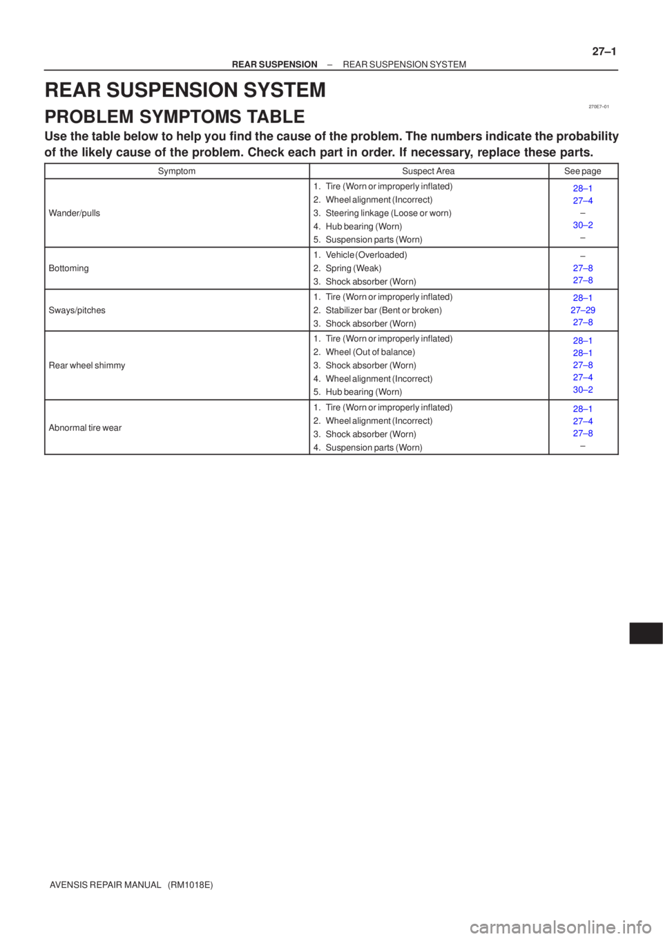
REAR SUSPENSION SYSTEM
PROBLEM SYMPTOMS TABLE
Use the table below to help you find the cause of the problem. The numbers \
indicate the probability
of the likely cause of the problem. Check each part in order. If necessary, replace these parts.
SymptomSuspect AreaSee page
Wander/pulls
1. Tire (Worn or improperly inflated)
2. Wheel alignment (Incorrect)
3. Steering linkage (Loose or worn)
4. Hub bearing (Worn)
5. Suspension parts (Worn)28±1
27±4
±
30±2 ±
Bottoming
1. Vehicle (Overloaded)
2. Spring (Weak)
3. Shock absorber (Worn)±
27±8
27±8
Sways/pitches
1. Tire (Worn or improperly inflated)
2. Stabilizer bar (Bent or broken)
3. Shock absorber (Worn)28±1
27±29 27±8
Rear wheel shimmy
1. Tire (Worn or improperly inflated)
2. Wheel (Out of balance)
3. Shock absorber (Worn)
4. Wheel alignment (Incorrect)
5. Hub bearing (Worn)28±1
28±1
27±8
27±4
30±2
Abnormal tire wear
1. Tire (Worn or improperly inflated)
2. Wheel alignment (Incorrect)
3. Shock absorber (Worn)
4. Suspension parts (Worn)28±1
27±4
27±8
±