Page 67 of 1690
3201A±12
± BRAKEBRAKE SYSTEM
32±1
AVENSIS REPAIR MANUAL (RM1018E)
BRAKE SYSTEM
PRECAUTION
�Care must be taken to replace each part properly as it could affect the performance of the brake
system and result in a driving hazard. Replace the ones with parts having the same part number
or equivalent.
�It is very important to keep the parts and the area clean when repairing the brake system.
�If the vehicle is equipped with a mobile communication system, refer to the precaution in the
INTRODUCTION.
Page 68 of 1690
3201B±12
32±2
±
BRAKE BRAKE SYSTEM
AVENSIS REPAIR MANUAL (RM1018E)
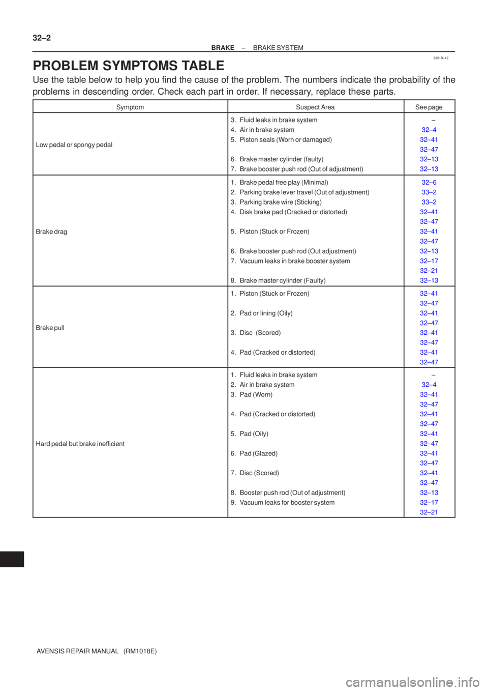
PROBLEM SYMPTOMS TABLE
Use the table below to help you find the cause of the problem. The numbers \
indicate the probability of the
problems in descending order. Check each part in order. If necessary, replace these parts.
SymptomSuspect AreaSee page
Low pedal or spongy pedal
3. Fluid leaks in brake system
4. Air in brake system
5. Piston seals (Worn or damaged)
6. Brake master cylinder (faulty)
7. Brake booster push rod (Out of adjustment) ±
32±4
32±41
32±47
32±13
32±13
Brake drag
1. Brake pedal free play (Minimal)
2. Parking brake lever travel (Out of adjustment)
3. Parking brake wire (Sticking)
4. Disk brake pad (Cracked or distorted)
5. Piston (Stuck or Frozen)
6. Brake booster push rod (Out adjustment)
7. Vacuum leaks in brake booster system
8. Brake master cylinder (Faulty)32±6
33±2
33±2
32±41
32±47
32±41
32±47
32±13
32±17
32±21
32±13
Brake pull
1. Piston (Stuck or Frozen)
2. Pad or lining (Oily)
3. Disc (Scored)
4. Pad (Cracked or distorted) 32±41
32±47
32±41
32±47
32±41
32±47
32±41
32±47
Hard pedal but brake inefficient
1. Fluid leaks in brake system
2. Air in brake system
3. Pad (Worn)
4. Pad (Cracked or distorted)
5. Pad (Oily)
6. Pad (Glazed)
7. Disc (Scored)
8. Booster push rod (Out of adjustment)
9. Vacuum leaks for booster system ±
32±4
32±41
32±47
32±41
32±47
32±41
32±47
32±41
32±47
32±41
32±47
32±13
32±17
32±21
Page 122 of 1690
4200B±04
±
CLUTCH CLUTCH SYSTEM (MTM)
42±1
AVENSIS REPAIR MANUAL (RM1018E)
CLUTCH SYSTEM (MTM)
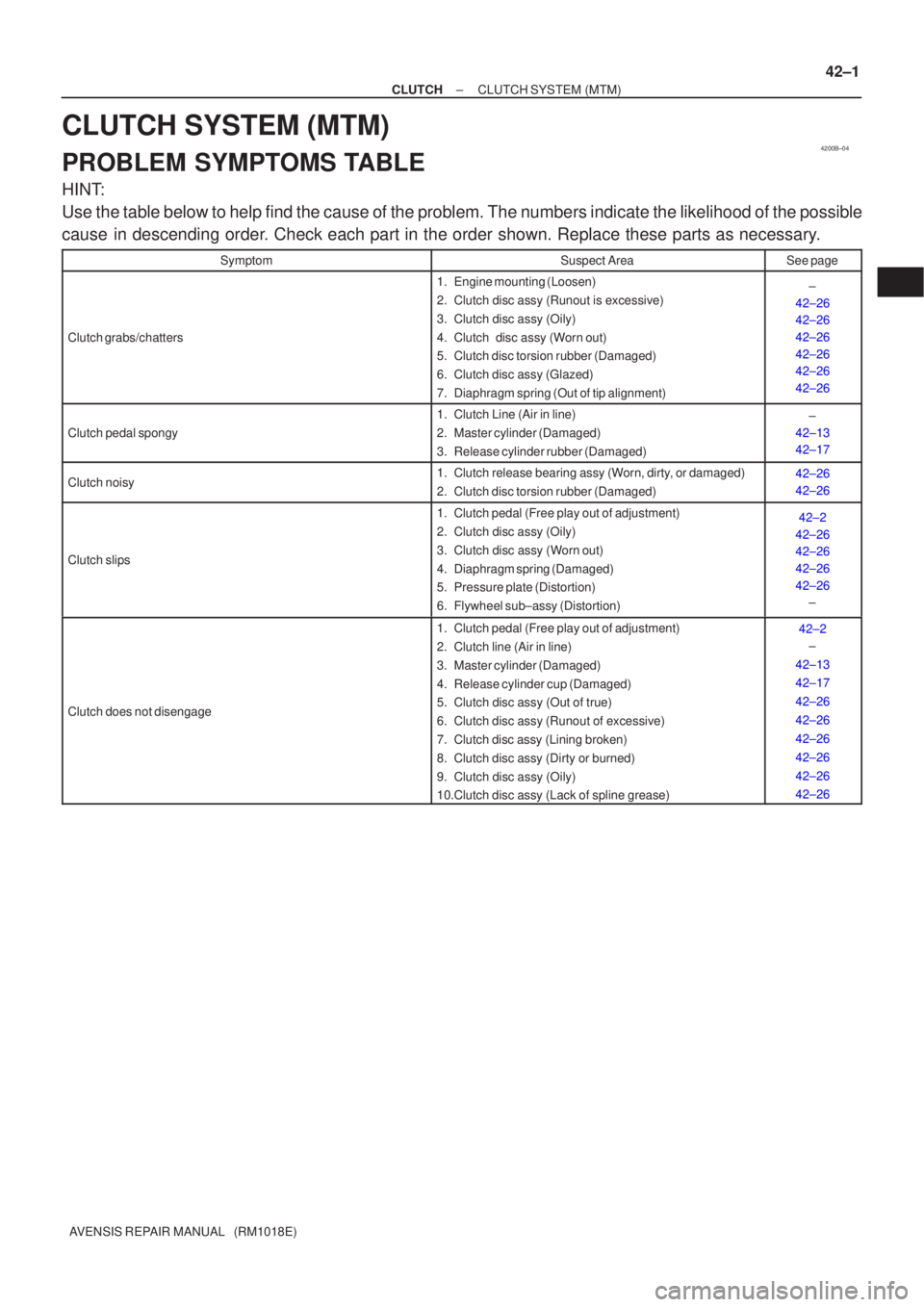
PROBLEM SYMPTOMS TABLE
HINT:
Use the table below to help find the cause of the problem. The numbers indi\
cate the likelihood of the possible
cause in descending order. Check each part in the order shown. Replace these parts as necessary.
SymptomSuspect AreaSee page
Clutch grabs/chatters
1. Engine mounting (Loosen)
2. Clutch disc assy (Runout is excessive)
3. Clutch disc assy (Oily)
4. Clutch disc assy (Worn out)
5. Clutch disc torsion rubber (Damaged)
6. Clutch disc assy (Glazed)
7. Diaphragm spring (Out of tip alignment)±
42±26
42±26
42±26
42±26
42±26
42±26
Clutch pedal spongy
1. Clutch Line (Air in line)
2. Master cylinder (Damaged)
3. Release cylinder rubber (Damaged)±
42±13
42±17
Clutch noisy1. Clutch release bearing assy (Worn, dirty, or damaged)
2. Clutch disc torsion rubber (Damaged)42±26
42±26
Clutch slips
1. Clutch pedal (Free play out of adjustment)
2. Clutch disc assy (Oily)
3. Clutch disc assy (Worn out)
4. Diaphragm spring (Damaged)
5. Pressure plate (Distortion)
6. Flywheel sub±assy (Distortion)42±2
42±26
42±26
42±26
42±26 ±
Clutch does not disengage
1. Clutch pedal (Free play out of adjustment)
2. Clutch line (Air in line)
3. Master cylinder (Damaged)
4. Release cylinder cup (Damaged)
5. Clutch disc assy (Out of true)
6. Clutch disc assy (Runout of excessive)
7. Clutch disc assy (Lining broken)
8. Clutch disc assy (Dirty or burned)
9. Clutch disc assy (Oily)
10.Clutch disc assy (Lack of spline grease)42±2
±
42±13
42±17
42±26
42±26
42±26
42±26
42±26
42±26
Page 148 of 1690
160N2±01
P13560
P00436
10mm
A51911
± COOLINGCOOLING SYSTEM (1AZ±FE)
16±15
AVENSIS REPAIR MANUAL (RM1018E)
INSPECTION
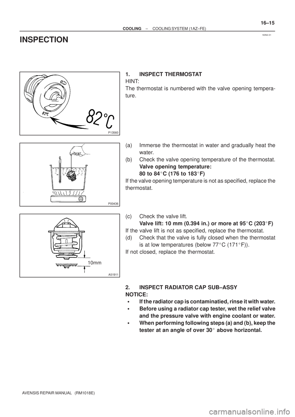
1. INSPECT THERMOSTAT
HINT:
The thermostat is numbered with the valve opening tempera-
ture.
(a) Immerse the thermostat in water and gradually heat the
water.
(b) Check the valve opening temperature of the thermostat.
Valve opening temperature:
80 to 84�C (176 to 183�F)
If the valve opening temperature is not as specified, replace the
thermostat.
(c) Check the valve lift.
Valve lift: 10 mm (0.394 in.) or more at 95�C (203�F)
If the valve lift is not as specified, replace the thermostat.
(d) Check that the valve is fully closed when the thermostat
is at low temperatures (below 77�C (171�F)).
If not closed, replace the thermostat.
2. INSPECT RADIATOR CAP SUB±ASSY
NOTICE:
�If the radiator cap is contaminatied, rinse it with water.
�Before using a radiator cap tester, wet the relief valve
and the pressure valve with engine coolant or water.
�When performing following steps (a) and (b), keep the
tester at an angle of over 30� above horizontal.
Page 152 of 1690
160MZ±01
P35001
P00436
10mm
A51911
± COOLINGCOOLING SYSTEM (1AZ±FSE)
16±27
AVENSIS REPAIR MANUAL (RM1018E)
INSPECTION
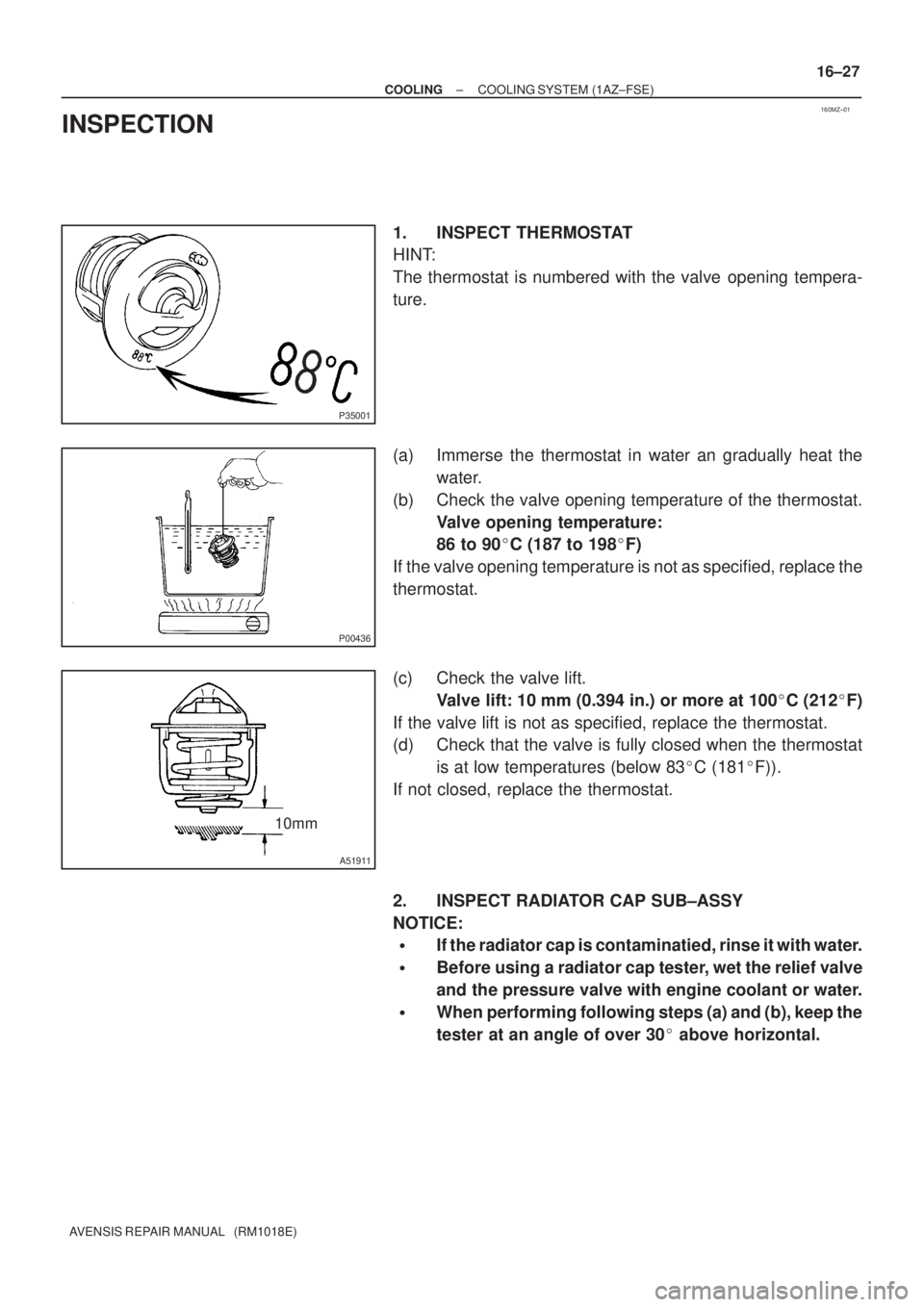
1. INSPECT THERMOSTAT
HINT:
The thermostat is numbered with the valve opening tempera-
ture.
(a) Immerse the thermostat in water an gradually heat the
water.
(b) Check the valve opening temperature of the thermostat.
Valve opening temperature:
86 to 90�C (187 to 198�F)
If the valve opening temperature is not as specified, replace the
thermostat.
(c) Check the valve lift.
Valve lift: 10 mm (0.394 in.) or more at 100�C (212�F)
If the valve lift is not as specified, replace the thermostat.
(d) Check that the valve is fully closed when the thermostat
is at low temperatures (below 83�C (181�F)).
If not closed, replace the thermostat.
2. INSPECT RADIATOR CAP SUB±ASSY
NOTICE:
�If the radiator cap is contaminatied, rinse it with water.
�Before using a radiator cap tester, wet the relief valve
and the pressure valve with engine coolant or water.
�When performing following steps (a) and (b), keep the
tester at an angle of over 30� above horizontal.
Page 156 of 1690
160N7±01
B08008
CO0929
B08007
8.5mm
± COOLINGCOOLING SYSTEM (1CD±FTV)
16±39
AVENSIS REPAIR MANUAL (RM1018E)
INSPECTION
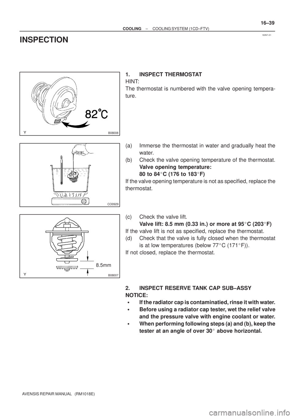
1. INSPECT THERMOSTAT
HINT:
The thermostat is numbered with the valve opening tempera-
ture.
(a) Immerse the thermostat in water and gradually heat the
water.
(b) Check the valve opening temperature of the thermostat.
Valve opening temperature:
80 to 84�C (176 to 183�F)
If the valve opening temperature is not as specified, replace the
thermostat.
(c) Check the valve lift.
Valve lift: 8.5 mm (0.33 in.) or more at 95�C (203�F)
If the valve lift is not as specified, replace the thermostat.
(d) Check that the valve is fully closed when the thermostat
is at low temperatures (below 77�C (171�F)).
If not closed, replace the thermostat.
2. INSPECT RESERVE TANK CAP SUB±ASSY
NOTICE:
�If the radiator cap is contaminatied, rinse it with water.
�Before using a radiator cap tester, wet the relief valve
and the pressure valve with engine coolant or water.
�When performing following steps (a) and (b), keep the
tester at an angle of over 30� above horizontal.
Page 188 of 1690
3005C±02
±
DRIVE SHAFT / PROPELLER SHAFT DRIVE SHAFT, PROPELLER SHAFT, AXLE
30±1
AVENSIS REPAIR MANUAL (RM1018E)
DRIVE SHAFT, PROPELLER SHAFT, AXLE
PROBLEM SYMPTOMS TABLE
Use the table below to help you find the cause of the problem. The numbers \
indicate the priority of
the likely cause of the problem. Check each part in order. If necessary, replace these parts.
SymptomSuspect AreaSee page
Wander
5. Wheel
6. Front wheel alignment
7. Rear wheel alignment
8. Hub bearing (Worn)
9. Front shock absorber
10.Rear shock absorber28±1
26±6
27±4
30±2
26±10
27±8
Front wheel shimmy
1. Wheel (Imbalance)
2. Hub bearing (Worn)
3. Lower suspension arm ATM:
4. Lower suspension arm MTM:
5. Lower ball joint (Worm)
6. Front shock absorber28±1
30±2
26±16
26±21
26±24
26±10
Noise (Front)
1. Front drive shaft
2. Front shock absorber
3. Hub bearing (Worn)
4. Lower ball joint (Worm)30±6
26±10 30±2
26±24
Noise (Rear)1. Hub bearing (Worn)
2. Rear shock absorber30±2
27±8
Page 342 of 1690
A77284
A77415Bearing Cap No. 1Bearing Cap No. 3 5
312 4
A52473
A77416
Bearing Cap No. 2 Bearing Cap No. 3
531 2 4
A77417
TightenHold
± ENGINE MECHANICALCAMSHAFT (1AZ±FE)
14±175
AVENSIS REPAIR MANUAL (RM1018E)
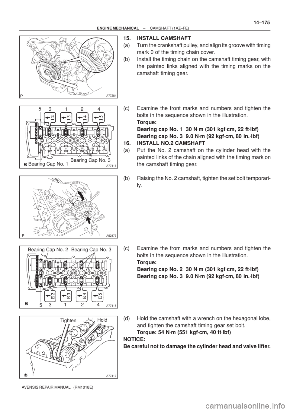
15. INSTALL CAMSHAFT
(a) Turn the crankshaft pulley, and align its groove with timing
mark 0 of the timing chain cover.
(b) Install the timing chain on the camshaft timing gear, with
the painted links aligned with the timing marks on the
camshaft timing gear.
(c) Examine the front marks and numbers and tighten the
bolts in the sequence shown in the illustration.
Torque:
Bearing cap No. 1 30 N�m (301 kgf�cm, 22 ft�lbf)
Bearing cap No. 3 9.0 N�m (92 kgf�cm, 80 in.�lbf)
16. INSTALL NO.2 CAMSHAFT
(a) Put the No. 2 camshaft on the cylinder head with the
painted links of the chain aligned with the timing mark on
the camshaft timing gear.
(b) Raising the No. 2 camshaft, tighten the set bolt temporari-
ly.
(c) Examine the from marks and numbers and tighten the
bolts in the sequence shown in the illustration.
Torque:
Bearing cap No. 2 30 N�m (301 kgf�cm, 22 ft�lbf)
Bearing cap No. 3 9.0 N�m (92 kgf�cm, 80 in.�lbf)
(d) Hold the camshaft with a wrench on the hexagonal lobe,
and tighten the camshaft timing gear set bolt.
Torque: 54 N�m (551 kgf�cm, 40 ft�lbf)
NOTICE:
Be careful not to damage the cylinder head and valve lifter.