Page 36 of 1690
320VZ±01
G24211
To Master Cylinder Front
G24212
To Master Cylinder Rear
To Front Wheel RH
To Rear Wheel LH
To Rear Wheel RH
To Front Wheel LH
G24213
32±54
± BRAKEBRAKE ACTUATOR ASSY (W/O VSC)
AVENSIS REPAIR MANUAL (RM1018E)
REPLACEMENT
1. DRAIN BRAKE FLUID
NOTICE:
Wash the brake fluid off immediately if it adheres to any painted surfaces.
2. REMOVE FRONT WHEEL RH
3. REMOVE FRONT FENDER LINER RH
4. REMOVE BRAKE ACTUATOR WITH BRACKET
(a) Release the latch of the brake actuator connector to dis-
connect the connector.
(b) Using SST, disconnect the brake tubes from the brake ac-
tuator.
SST 09023±00100
(c) Use tags or make a memo to identify the place to recon-
nect.
(d) Remove the nut, 2 bolts and brake actuator with bracket.
Page 58 of 1690
320W6±01
G24218
G24217
F45393
± BRAKEBRAKE MASTER CYLINDER SUB±ASSY
32±13
AVENSIS REPAIR MANUAL (RM1018E)
REPLACEMENT
NOTICE:
Do not adjust the brake booster push rod.
1. DRAIN BRAKE FLUID
NOTICE:
Wash the brake fluid off immediately if it adheres to any painted surface.
2. REMOVE ENGINE ROOM RELAY BLOCK (LHD STEERING POSITION TYPE)
3. REMOVE AIR CLEANER CAP SUB±ASSY (LHD STEERING POSITION TYPE)
4. REMOVE CHARCOAL CANISTER ASSY (LHD STEERING POSITION TYPE)
5. REMOVE FUEL FILTER ASSY (LHD STEERING POSITION TYPE)
(a) Diesal engine type:
Remove the fuel filter assy with the 3 bolts.
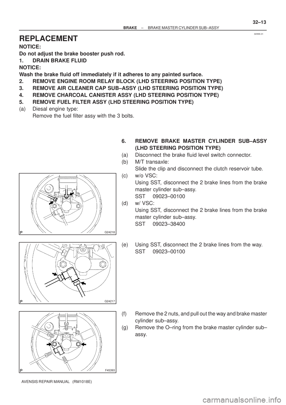
6. REMOVE BRAKE MASTER CYLINDER SUB±ASSY
(LHD STEERING POSITION TYPE)
(a) Disconnect the brake fluid level switch connector.
(b) M/T transaxle:
Slide the clip and disconnect the clutch reservoir tube.
(c) w/o VSC:
Using SST, disconnect the 2 brake lines from the brake
master cylinder sub±assy.
SST 09023±00100
(d) w/ VSC:
Using SST, disconnect the 2 brake lines from the brake
master cylinder sub±assy.
SST 09023±38400
(e) Using SST, disconnect the 2 brake lines from the way.
SST 09023±00100
(f) Remove the 2 nuts, and pull out the way and brake master
cylinder sub±assy.
(g) Remove the O±ring from the brake master cylinder sub±
assy.
Page 71 of 1690
320W1±01
F45421
Union Bolt
G23232
F45419
Cylinder Slide Pin
F45417
Cylinder Slide Bush
Cylinder Slide Pin (No.2)
± BRAKEFRONT BRAKE
32±41
AVENSIS REPAIR MANUAL (RM1018E)
OVERHAUL
HINT:
Overhaul the RH side by using the same procedures as those for the LH side.
1. REMOVE FRONT WHEEL
2. DRAIN BRAKE FLUID
NOTICE:
Wash the brake fluid off immediately if it adheres to any painted surface.
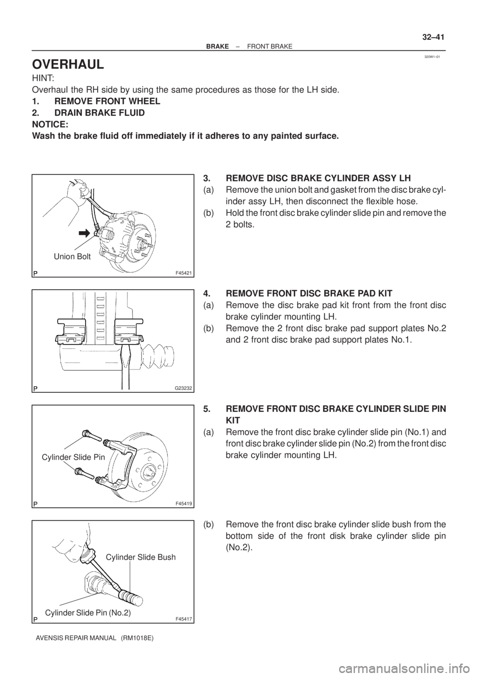
3. REMOVE DISC BRAKE CYLINDER ASSY LH
(a) Remove the union bolt and gasket from the disc brake cyl-
inder assy LH, then disconnect the flexible hose.
(b) Hold the front disc brake cylinder slide pin and remove the
2 bolts.
4. REMOVE FRONT DISC BRAKE PAD KIT
(a) Remove the disc brake pad kit front from the front disc
brake cylinder mounting LH.
(b) Remove the 2 front disc brake pad support plates No.2
and 2 front disc brake pad support plates No.1.
5. REMOVE FRONT DISC BRAKE CYLINDER SLIDE PIN
KIT
(a) Remove the front disc brake cylinder slide pin (No.1) and
front disc brake cylinder slide pin (No.2) from the front disc
brake cylinder mounting LH.
(b) Remove the front disc brake cylinder slide bush from the
bottom side of the front disk brake cylinder slide pin
(No.2).
Page 77 of 1690
320W0±01
G23181
Union bolt
G23224
F45701
Cylinder Slide Pin
F45417
Cylinder Slide Bush
Cylinder Slide Pin (No.2)
± BRAKEREAR BRAKE
32±47
AVENSIS REPAIR MANUAL (RM1018E)
OVERHAUL
HINT:
Overhaul the RH side by using the same procedures as those for the LH side.
1. REMOVE REAR WHEEL
2. DRAIN BRAKE FLUID
NOTICE:
Wash the brake fluid off immediately if it adheres to any painted surface.
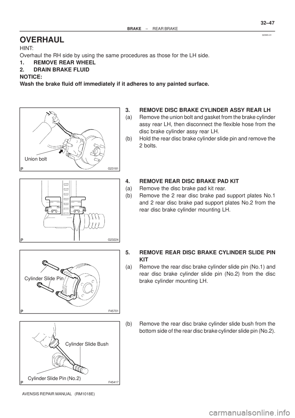
3. REMOVE DISC BRAKE CYLINDER ASSY REAR LH
(a) Remove the union bolt and gasket from the brake cylinder
assy rear LH, then disconnect the flexible hose from the
disc brake cylinder assy rear LH.
(b) Hold the rear disc brake cylinder slide pin and remove the
2 bolts.
4. REMOVE REAR DISC BRAKE PAD KIT
(a) Remove the disc brake pad kit rear.
(b) Remove the 2 rear disc brake pad support plates No.1
and 2 rear disc brake pad support plates No.2 from the
rear disc brake cylinder mounting LH.
5. REMOVE REAR DISC BRAKE CYLINDER SLIDE PIN
KIT
(a) Remove the rear disc brake cylinder slide pin (No.1) and
rear disc brake cylinder slide pin (No.2) from the disc
brake cylinder mounting LH.
(b) Remove the rear disc brake cylinder slide bush from the
bottom side of the rear disc brake cylinder slide pin (No.2).
Page 144 of 1690
160MK±01
A76724
A79300Upper Hook
±
COOLING RADIATOR ASSY(1ZZ±FE/3ZZ±FE)
16±11
AVENSIS REPAIR MANUAL (RM1018E)
RADIATOR ASSY(1ZZ±FE/3ZZ±FE)
REPLACEMENT
1.REMOVE RADIATOR SUPPORT OPENING COVER (See page 14±27)
2.REMOVE ENGINE ROOM COVER SIDE (See page 14±27)
3.ENGINE UNDER COVER SUB±ASSY NO.1 (See page 14±27)
4.DRAIN ENGINE COOLANT (See page 16±1)
5. DISCONNECT RADIATOR HOSE INLET
(a) Disconnect the radiator hose inlet from the radiator.
6. DISCONNECT RADIATOR HOSE OUTLET
(a) Disconnect the radiator hose outlet from the radiator.
7. DISCONNECT OIL COOLER INLET TUBE NO.1 (A/T TRANSAXLE)
(a) Disconnect the oil cooler inlet tube from the radiator.
8. DISCONNECT OIL COOLER OUTLET TUBE NO.1 (A/T TRANSAXLE)
(a) Disconnect the oil cooler outlet tube from the radiator.
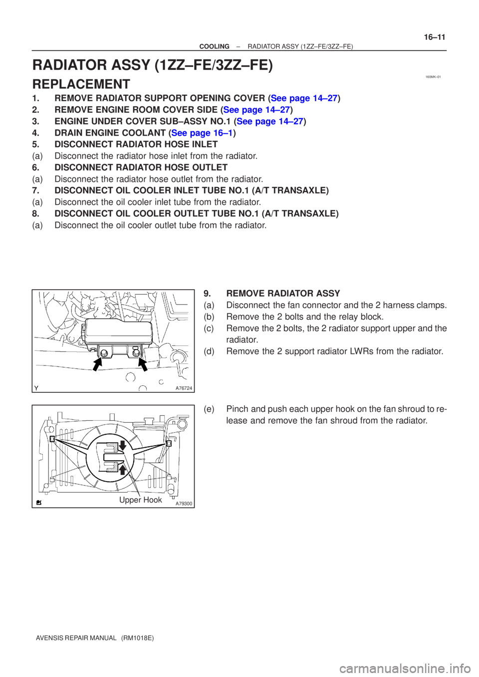
9. REMOVE RADIATOR ASSY
(a) Disconnect the fan connector and the 2 harness clamps.
(b) Remove the 2 bolts and the relay block.
(c) Remove the 2 bolts, the 2 radiator support upper and theradiator.
(d) Remove the 2 support radiator LWRs from the radiator.
(e) Pinch and push each upper hook on the fan shroud to re- lease and remove the fan shroud from the radiator.
Page 170 of 1690
160MX±01
16±24
±
COOLING RADIATOR ASSY(1AZ±FE)
AVENSIS REPAIR MANUAL (RM1018E)
RADIATOR ASSY(1AZ±FE)
REPLACEMENT
1.DRAIN COOLANT (See page 16±19)
2.REMOVE RADIATOR SUPPORT OPENING COVER
3.REMOVE ENGINE ROOM COVER SIDE
4.REMOVE ENGINE UNDER COVER RH
5.DISCONNECT RADIATOR HOSE INLET
6.DISCONNECT RADIATOR HOSE OUTLET
7.REMOVE RADIATOR SUPPORT UPPER
(a)Disconnect the fan w/ motor wire harness, connector and the horn connect\
or.
(b)Remove 4 bolts, the nut and the radiator support.
8.REMOVE RADIATOR ASSY
(a)Remove 2 upper support, and radiator assembly
9.REMOVE RADIATOR SUPPORT LOWER
10.REMOVE FAN ASSY W/MOTOR
(a)Remove 6 bolts and fan w/motor.
11.INSTALL FAN ASSY W/MOTOR
12.INSTALL RADIATOR SUPPORT LOWER
13.INSTALL RADIATOR ASSY
14.INSTALL RADIATOR SUPPORT UPPER
(a)Install radiator support with 2 bolts. Torque: 19 N �m (194 kgf �cm,14 ft �lbf)
15.ADD COOLANT (See page 16±19)
16.INSPECT CHECK FOR ENGINE COOLANT LEAKS (See page 16±13)
Page 171 of 1690
160MS±01
16±36
±
COOLING RADIATOR ASSY(1AZ±FSE)
AVENSIS REPAIR MANUAL (RM1018E)
RADIATOR ASSY(1AZ±FSE)
REPLACEMENT
1.DRAIN COOLANT (See page 16±31)
2.REMOVE RADIATOR SUPPORT OPENING COVER
3.REMOVE ENGINE ROOM COVER SIDE
4.REMOVE ENGINE UNDER COVER RH
5.DISCONNECT RADIATOR HOSE INLET
6.DISCONNECT RADIATOR HOSE OUTLET
7.REMOVE RADIATOR SUPPORT UPPER
(a)Disconnect the fan w/ motor wire harness, connector and the horn connect\
or.
(b)Remove 4 bolts, the nut and the radiator support.
8.REMOVE RADIATOR ASSY
(a)Remove 2 upper support, and radiator assembly
9.REMOVE RADIATOR SUPPORT LOWER
10.REMOVE FAN ASSY W/MOTOR
(a)Remove 6 bolts and fan w/motor.
11.INSTALL FAN ASSY W/MOTOR
12.INSTALL RADIATOR SUPPORT LOWER
13.INSTALL RADIATOR ASSY
14.INSTALL RADIATOR SUPPORT UPPER
(a)Install radiator support with 2 bolts. Torque: 19 N �m (194 kgf �cm,14 ft �lbf)
15.ADD COOLANT (See page 16±31)
16.INSPECT CHECK FOR ENGINE COOLANT LEAKS (See page 16±25)
Page 172 of 1690
160MG±01
±
COOLING RADIATOR ASSY(1CD±FTV)
16±51
AVENSIS REPAIR MANUAL (RM1018E)
RADIATOR ASSY(1CD±FTV)
REPLACEMENT
1.DRAIN ENGINE COOLANT(See page 16±44)
2.REMOVE RADIATOR SUPPORT OPENING COVER
3.REMOVE ENGINE ROOM COVER SIDE
4.REMOVE RADIATOR RESERVE TANK ASSY(See page 16±50)
5.DISCONNECT RADIATOR HOSE INLET
6.DISCONNECT RADIATOR HOSE OUTLET
7.REMOVE RADIATOR ASSY
(a)Remove the 2 bolts and separate the relay box.
(b)Remove the 2 upper support and radiator assy.
8.REMOVE RADIATOR SUPPORT LOWER
9.REMOVE FAN ASSY W/MOTOR
(a)Remove the 2 bolts and the fan w/motor.
10.INSTALL FAN ASSY W/MOTOR
Torque: 7.5 N �m (76 kgf �cm, 66 in. �lbf)
11.INSTALL RADIATOR ASSY
(a)Install the 2 upper support and the radiator assembly to the vehicle. Torque: 19 N �m (194 kgf �cm, 14 ft �lbf)
(b)Install the 2 bolts and the relay box.
Torque: 5.3 N �m (54 kgf �cm, 47 in. �lbf)
12.INSTALL RADIATOR RESERVE TANK ASSY(See page 16±50)
13.ADD ENGINE COOLANT(See page 16±44)
14.CHECK FOR ENGINE COOLANT LEAKS(See page 16±44)