Page 39 of 1690
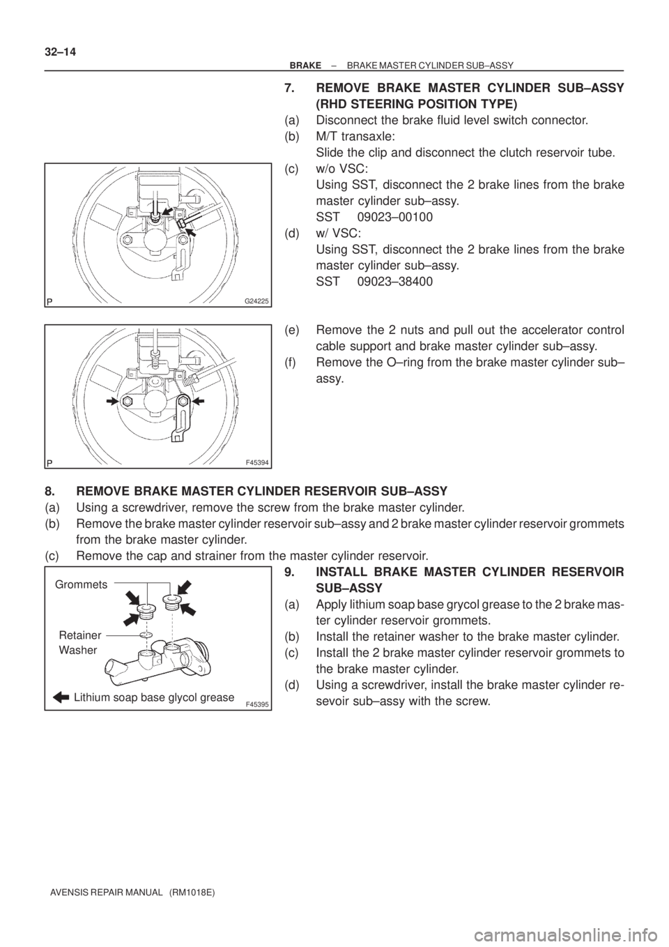
320VU±01
F45162
Vacuum Hose
ClipBrake Vacuum
Check Valve
Check Valve
Grommet
Clevis Pin
Clip Wave Washer
13 (130, 9)
Engine Room Relay Block Way
Clutch Reservoir Tube M/T Transaxle:
Front Brake
Tube No.5
15 (155, 11) *1
29 (296, 21) *2
Brake Fluid Level
Switch Connector
� Brake Booster Gasket
20 (204, 15)
20 (204, 15)
Brake Master
Cylinder Sub±assy
� Brake Booster Assy
Brake Master
Cylinder clevis
15 (155, 11)
Fuel Filter Assy Diesel Engine Type: Heater Assy w/ Cold Area:
Air Cleaner Assembly
With Hose
Clutch Tube M/T Transaxle:Gasoline Engine Type:
15 (155, 11)
*1
w/ ABS:
*2
w/ VSC:N�m (kgf�cm, ft�lbf) : Specified torque
5.4 (55, 48 in.�lbf)
Charcoal Canister
Assy
32±18
± BRAKEBRAKE BOOSTER ASSY (LHD)
AVENSIS REPAIR MANUAL (RM1018E)
COMPONENTS
Page 59 of 1690

G24225
F45394
F45395Lithium soap base glycol grease
Grommets
Retainer
Washer
32±14
± BRAKEBRAKE MASTER CYLINDER SUB±ASSY
AVENSIS REPAIR MANUAL (RM1018E)
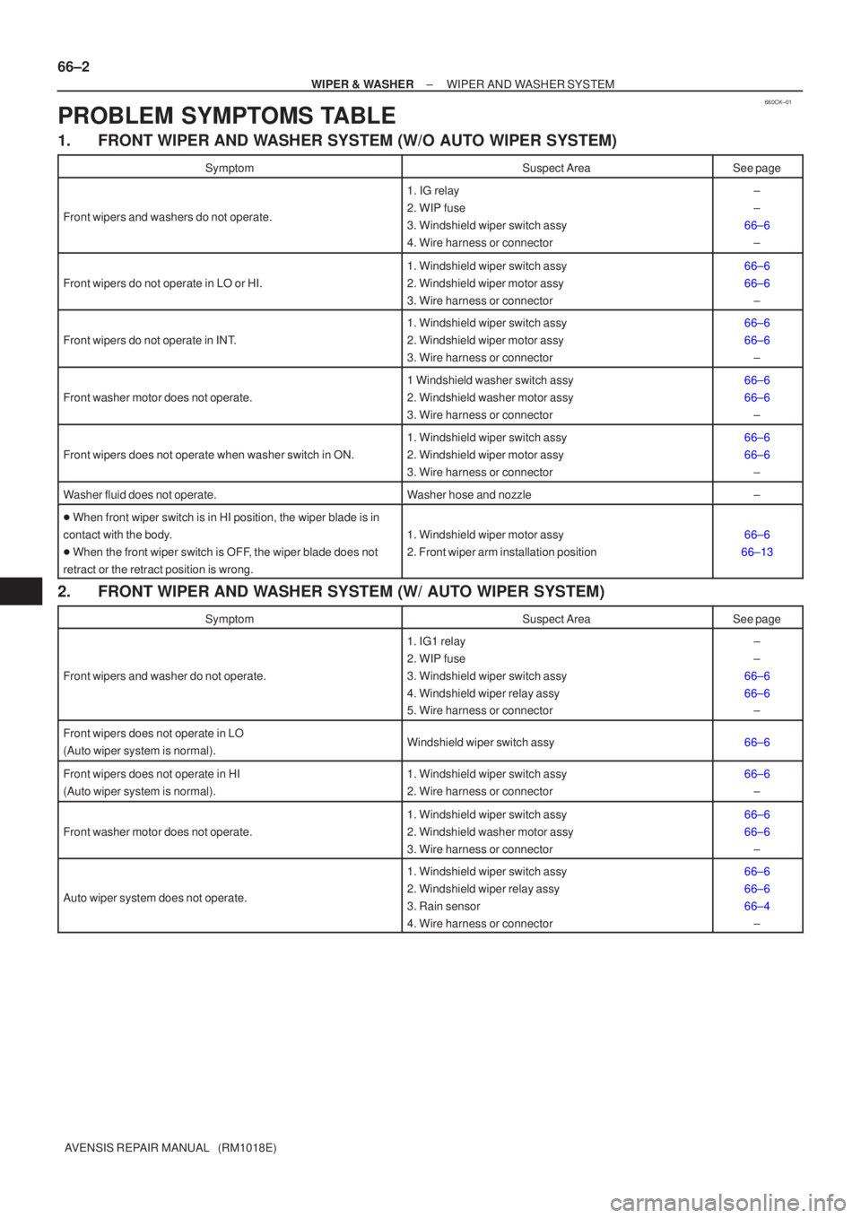
7. REMOVE BRAKE MASTER CYLINDER SUB±ASSY
(RHD STEERING POSITION TYPE)
(a) Disconnect the brake fluid level switch connector.
(b) M/T transaxle:
Slide the clip and disconnect the clutch reservoir tube.
(c) w/o VSC:
Using SST, disconnect the 2 brake lines from the brake
master cylinder sub±assy.
SST 09023±00100
(d) w/ VSC:
Using SST, disconnect the 2 brake lines from the brake
master cylinder sub±assy.
SST 09023±38400
(e) Remove the 2 nuts and pull out the accelerator control
cable support and brake master cylinder sub±assy.
(f) Remove the O±ring from the brake master cylinder sub±
assy.
8. REMOVE BRAKE MASTER CYLINDER RESERVOIR SUB±ASSY
(a) Using a screwdriver, remove the screw from the brake master cylinder.
(b) Remove the brake master cylinder reservoir sub±assy and 2 brake master cylinder reservoir grommets
from the brake master cylinder.
(c) Remove the cap and strainer from the master cylinder reservoir.
9. INSTALL BRAKE MASTER CYLINDER RESERVOIR
SUB±ASSY
(a) Apply lithium soap base grycol grease to the 2 brake mas-
ter cylinder reservoir grommets.
(b) Install the retainer washer to the brake master cylinder.
(c) Install the 2 brake master cylinder reservoir grommets to
the brake master cylinder.
(d) Using a screwdriver, install the brake master cylinder re-
sevoir sub±assy with the screw.
Page 1664 of 1690
660CU±01
I35778
A: 150 mm (5.91 in.)
B: 50 mm (1.97 in.)
C: 480 mm (18.90 in.)
D: 295 mm (11.61 in.)
E: 310 mm (12.21 in.)F: 275 mm (10.83 in.)
G: 130 mm (5.12 in.)
H: 420 mm (16.54 in.)
I: 280 mm (11.02 in.) Front:
AB
C
DE
FG
HI
A
A
A
B
B
B
C 66±22
± WIPER & WASHERWASHER NOZZLE SUB±ASSY
AVENSIS REPAIR MANUAL (RM1018E)
WASHER NOZZLE SUB±ASSY
ADJUSTMENT
1. REMOVE WASHER NOZZLE SUB±ASSY
(a) With the engine running, check that the point where the washer fluid hits the windshield and the rear
window is within the range indicated by the hatched line.
Page 1669 of 1690
I34456
17.5 ± 32.5 mm
(0.69 ± 1.28 in.)
Cowl top ventilator louver
66±16
± WIPER & WASHERWINDSHIELD WIPER MOTOR ASSY
AVENSIS REPAIR MANUAL (RM1018E)
10. INSTALL FR WIPER ARM RH
(a) Scrape off the serration part of the wiper arm with a round
file or equivalent.
(b) Clean the wiper pivot serration with a wire brush.
(c) Install the front wiper arm RH with the nut to the position
shown in the illustration.
Torque: 21 N�m (210 kgf�cm, 15 ft�lbf)
HINT:
Hold down the arm hinge by hand to fasten the nut.
(d) Operate the wiper while running the water or the washer
fluid over the window, and check the wiping condition and
that the front wiper does not hit against the vehicle body.
Page 1672 of 1690

660CK±01
66±2
±
WIPER & WASHER WIPER AND WASHER SYSTEM
AVENSIS REPAIR MANUAL (RM1018E)
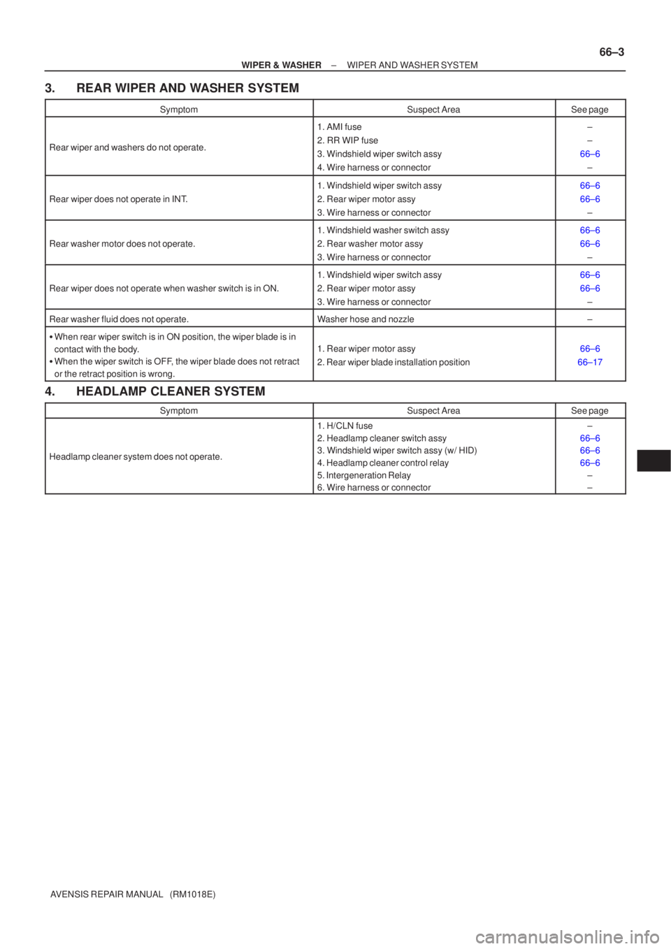
PROBLEM SYMPTOMS TABLE
1.FRONT WIPER AND WASHER SYSTEM (W/O AUTO WIPER SYSTEM)
SymptomSuspect AreaSee page
Front wipers and washers do not operate.
1. IG relay
2. WIP fuse
3. Windshield wiper switch assy
4. Wire harness or connector±
±
66±6 ±
Front wipers do not operate in LO or HI.
1. Windshield wiper switch assy
2. Windshield wiper motor assy
3. Wire harness or connector66±6
66±6±
Front wipers do not operate in INT.
1. Windshield wiper switch assy
2. Windshield wiper motor assy
3. Wire harness or connector66±6
66±6±
Front washer motor does not operate.
1 Windshield washer switch assy
2. Windshield washer motor assy
3. Wire harness or connector66±6
66±6±
Front wipers does not operate when washer switch in ON.
1. Windshield wiper switch assy
2. Windshield wiper motor assy
3. Wire harness or connector66±6
66±6±
Washer fluid does not operate.Washer hose and nozzle±
� When front wiper switch is in HI position, the wiper blade is in
contact with the body.
� When the front wiper switch is OFF, the wiper blade does not
retract or the retract position is wrong.
1. Windshield wiper motor assy
2. Front wiper arm installation position66±6
66±13
2. FRONT WIPER AND WASHER SYSTEM (W/ AUTO WIPER SYSTEM)
SymptomSuspect AreaSee page
Front wipers and washer do not operate.
1. IG1 relay
2. WIP fuse
3. Windshield wiper switch assy
4. Windshield wiper relay assy
5. Wire harness or connector±
±
66±6
66±6 ±
Front wipers does not operate in LO
(Auto wiper system is normal).Windshield wiper switch assy66±6
Front wipers does not operate in HI
(Auto wiper system is normal).1. Windshield wiper switch assy
2. Wire harness or connector66±6
±
Front washer motor does not operate.
1. Windshield wiper switch assy
2. Windshield washer motor assy
3. Wire harness or connector66±6
66±6±
Auto wiper system does not operate.
1. Windshield wiper switch assy
2. Windshield wiper relay assy
3. Rain sensor
4. Wire harness or connector66±6
66±6
66±4±
Page 1673 of 1690

±
WIPER & WASHER WIPER AND WASHER SYSTEM
66±3
AVENSIS REPAIR MANUAL (RM1018E)
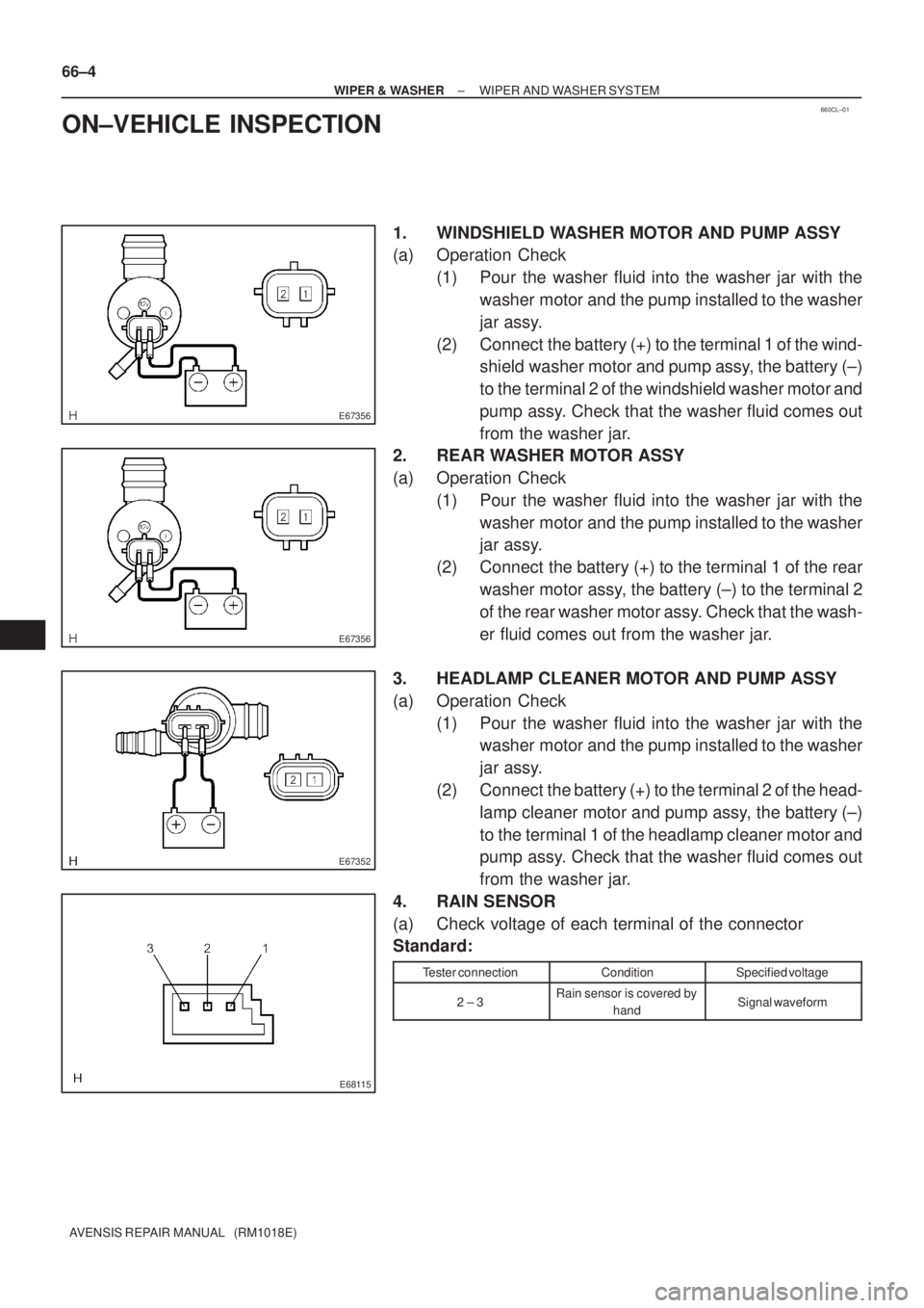
3. REAR WIPER AND WASHER SYSTEM
SymptomSuspect AreaSee page
Rear wiper and washers do not operate.
1. AMI fuse
2. RR WIP fuse
3. Windshield wiper switch assy
4. Wire harness or connector±
±
66±6 ±
Rear wiper does not operate in INT.
1. Windshield wiper switch assy
2. Rear wiper motor assy
3. Wire harness or connector66±6
66±6±
Rear washer motor does not operate.
1. Windshield washer switch assy
2. Rear washer motor assy
3. Wire harness or connector66±6
66±6±
Rear wiper does not operate when washer switch is in ON.
1. Windshield wiper switch assy
2. Rear wiper motor assy
3. Wire harness or connector66±6
66±6±
Rear washer fluid does not operate.Washer hose and nozzle±
�When rear wiper switch is in ON position, the wiper blade is in
contact with the body.
� When the wiper switch is OFF, the wiper blade does not retract
or the retract position is wrong.
1. Rear wiper motor assy
2. Rear wiper blade installation position66±6
66±17
4. HEADLAMP CLEANER SYSTEM
SymptomSuspect AreaSee page
Headlamp cleaner system does not operate.
1. H/CLN fuse
2. Headlamp cleaner switch assy
3. Windshield wiper switch assy (w/ HID)
4. Headlamp cleaner control relay
5. Intergeneration Relay
6. Wire harness or connector±
66±6
66±6
66±6 ±
±
Page 1674 of 1690

660CL±01
E67356
E67356
E67352
E68115
66±4
± WIPER & WASHERWIPER AND WASHER SYSTEM
AVENSIS REPAIR MANUAL (RM1018E)
ON±VEHICLE INSPECTION
1. WINDSHIELD WASHER MOTOR AND PUMP ASSY
(a) Operation Check
(1) Pour the washer fluid into the washer jar with the
washer motor and the pump installed to the washer
jar assy.
(2) Connect the battery (+) to the terminal 1 of the wind-
shield washer motor and pump assy, the battery (±)
to the terminal 2 of the windshield washer motor and
pump assy. Check that the washer fluid comes out
from the washer jar.
2. REAR WASHER MOTOR ASSY
(a) Operation Check
(1) Pour the washer fluid into the washer jar with the
washer motor and the pump installed to the washer
jar assy.
(2) Connect the battery (+) to the terminal 1 of the rear
washer motor assy, the battery (±) to the terminal 2
of the rear washer motor assy. Check that the wash-
er fluid comes out from the washer jar.
3. HEADLAMP CLEANER MOTOR AND PUMP ASSY
(a) Operation Check
(1) Pour the washer fluid into the washer jar with the
washer motor and the pump installed to the washer
jar assy.
(2) Connect the battery (+) to the terminal 2 of the head-
lamp cleaner motor and pump assy, the battery (±)
to the terminal 1 of the headlamp cleaner motor and
pump assy. Check that the washer fluid comes out
from the washer jar.
4. RAIN SENSOR
(a) Check voltage of each terminal of the connector
Standard:
Tester connectionConditionSpecified voltage
2 ± 3Rain sensor is covered by
handSignal waveform