Page 56 of 1690
320W5±01
G24285
LHD Steering Position Type:
Charcoal Canister Assy
Brake Fluid Level
Switch Connector
Clutch Reservoir
Tube M/T Transaxle:Brake Booster Assy
Clip
Way
20 (204, 15)
15 (155, 11)
15 (155, 11)*1
29 (296, 21)*2
15 (155, 11)*1
29 (296, 21)*2
Brake Master
Cylinder Sub±assy
20 (204, 15)
Engin Room Relay Block
RHD Steering Position Type:Air Cleaner Cap Sub±assy
Brake Fluid Level
Switch ConnectorBrake Master
Cylinder Sub±assy
Clip
Accelerator Control
Cable Support
20 (204, 15)
*1
w/ ABS:*2 w/ VSC:N�m (kgf�cm, ft�lbf) : Specified torque
15 (155, 11)*1
29 (296, 21)*2
15 (155, 11)*1
29 (296, 21)*2
Clutch Reservoir
Tube M/T Transaxle:
Brake Booster Assy
5.4 (55, 48 in.�lbf)
Fuel Filter Assy Diesel Engin Type:
± BRAKEBRAKE MASTER CYLINDER SUB±ASSY
32±11
AVENSIS REPAIR MANUAL (RM1018E)
BRAKE MASTER CYLINDER SUB±ASSY
COMPONENTS
Page 58 of 1690

REPLACEMENT
NOTICE:
Do not adjust the brake booster push rod.
1. DRAIN BRAKE FLUID
NOTIC")
320W6±01
G24218
G24217
F45393
± BRAKEBRAKE MASTER CYLINDER SUB±ASSY
32±13
AVENSIS REPAIR MANUAL (RM1018E)
REPLACEMENT
NOTICE:
Do not adjust the brake booster push rod.
1. DRAIN BRAKE FLUID
NOTICE:
Wash the brake fluid off immediately if it adheres to any painted surface.
2. REMOVE ENGINE ROOM RELAY BLOCK (LHD STEERING POSITION TYPE)
3. REMOVE AIR CLEANER CAP SUB±ASSY (LHD STEERING POSITION TYPE)
4. REMOVE CHARCOAL CANISTER ASSY (LHD STEERING POSITION TYPE)
5. REMOVE FUEL FILTER ASSY (LHD STEERING POSITION TYPE)
(a) Diesal engine type:
Remove the fuel filter assy with the 3 bolts.
6. REMOVE BRAKE MASTER CYLINDER SUB±ASSY
(LHD STEERING POSITION TYPE)
(a) Disconnect the brake fluid level switch connector.
(b) M/T transaxle:
Slide the clip and disconnect the clutch reservoir tube.
(c) w/o VSC:
Using SST, disconnect the 2 brake lines from the brake
master cylinder sub±assy.
SST 09023±00100
(d) w/ VSC:
Using SST, disconnect the 2 brake lines from the brake
master cylinder sub±assy.
SST 09023±38400
(e) Using SST, disconnect the 2 brake lines from the way.
SST 09023±00100
(f) Remove the 2 nuts, and pull out the way and brake master
cylinder sub±assy.
(g) Remove the O±ring from the brake master cylinder sub±
assy.
Page 61 of 1690

(c) w/o VSC: Using SST, connect the 2 brake lines to the brake master
cylinder sub±assy.
SST 09023±00100
Torq")
G24225
32±16
±
BRAKE BRAKE MASTER CYLINDER SUB±ASSY
AVENSIS REPAIR MANUAL (RM1018E)
(c) w/o VSC: Using SST, connect the 2 brake lines to the brake master
cylinder sub±assy.
SST 09023±00100
Torque: 15 N �m (155 kgf �cm, 11 ft �lbf)
(d) w/ VSC: Using SST, connect the 2 brake lines to the brake master
cylinder sub±assy.
SST 09023±38400
Torque: 29 N �m (296 kgf �cm, 21 ft �lbf)
(e) M/T transaxle: Slide the clip and connect the clutch reservoir tube.
(f) Connect the brake fluid level switch connector.
12. INSTALL CHARCOAL CANISTER ASSY (LHD STEERING POSITION TYPE)
13. INSTALL ENGINE ROOM RELAY BLOCK (LHD STEERING POSITION TYPE)
14. INSTALL AIR CLEANER CAP SUB±ASSY (LHD STEERING POSITION TYPE)
15. INSTALL FUEL FILTER ASSY (LHD STEERING POSITION TYPE)
16.FILL RESERVOIR WITH BRAKE FLUID (See page 32±4)
17.BLEED MASTER CYLINDER (See page 32±4)
(a) w/o VSC: SST 09023±00100
(b) w/ VSC: SST 09023±38400
18.BLEED BRAKE LINE (See page 32±4)
19.BLEED CLUTCH PIPE LINE (M/T TRANSAXLE) (See page 42±13)
20.CHECK FLUID LEVEL IN RESERVOIR (See page 32±4)
21. CHECK BRAKE FLUID LEAKAGE
Page 212 of 1690

AVENSIS REPAIR MANUAL (RM1018E)
IN")
1209F±02
A62250
Port A
Port BPort C
A60562
Cylinder Head Side
A60563
Intake Manifold Side
Gasket
B11870
12±8
± EMISSION CONTROLEMISSION CONTROL SYSTEM (1AZ±FE)
AVENSIS REPAIR MANUAL (RM1018E)
INSPECTION
1. INSPECT CHARCOAL CANISTER ASSY
(a) Inspect charcoal canister operation.
(1) Check the charcoal canister operation according to
the table below.
SST 09992±00242
Inspection:
Checking methodResult
Close ports B and C, then apply vacuum
to port ANo leaks
Close port C, then apply vacuum to port
AAir flows from port B
Close port C, then blow air into port AAir flows from port B
Blow air into port AAir flows from ports B and C
2. INSPECT VENTILATION VALVE SUB±ASSY
(a) Install clean hose to the PCV valve.
(b) Inspect the PCV valve operation.
(1) Blow air into the cylinder head side, and check that
air passes through easily.
CAUTION:
Do not suck air through the valve. If contains petroleum
substances and is harmful.
(2) Blow air into the intake manifold side, and check
that air passes through with difficulty.
If operation is not as specified, replace the PCV valve.
(c) Remove clean hose from the PCV valve.
3. INSPECT FUEL TANK CAP ASSY
(a) Visually check if the cap or gasket is deformed or dam-
aged.
If necessary, repair or replace the cap.
Page 217 of 1690

12±13
AVENSIS REPAIR MANUAL (RM1018E)")
1209H±02
A62250
Port A
Port BPort C
A60562
Cylinder Head Side
A60563
Intake Manifold Side
Gasket
B11870
± EMISSION CONTROLEMISSION CONTROL SYSTEM (1AZ±FSE)
12±13
AVENSIS REPAIR MANUAL (RM1018E)
INSPECTION
1. INSPECT CHARCOAL CANISTER ASSY
(a) Inspect charcoal canister operation.
(1) Check the charcoal canister operation according to
the table below.
SST 09992±00242
Checking methodResult
Close ports B and C, then apply vacuum
to port ANo leaks
Close port C, then apply vacuum to port
AAir flows from port B
Close port C, then blow air into port AAir flows from port B
Blow air into port AAir flows from ports B and C
2. INSPECT VENTILATION VALVE SUB±ASSY
(a) Install clean hose to the PCV valve.
(b) Inspect the PCV valve operation.
(1) Blow air into the cylinder head side, and check that
air passes through easily.
CAUTION:
Do not suck air through the valve. If contains petroleum
substances and is harmful.
(2) Blow air into the intake manifold side, and check
that air passes through with difficulty.
If operation is not as specified, replace the PCV valve.
(c) Remove clean hose from the PCV valve.
3. INSPECT FUEL TANK CAP ASSY
(a) Visually check if the cap or gasket is deformed or dam-
aged.
If necessary, repair or replace the cap.
Page 225 of 1690
B04812
Gasket
± EMISSION CONTROLEMISSION CONTROL SYSTEM (1ZZ±FE/3ZZ±FE)
12±5
AVENSIS REPAIR MANUAL (RM1018E)
5. INSPECT FUEL TANK CAP ASSY
(a) Visually check if the cap or gasket is deformed or dam-
aged.
Page 241 of 1690
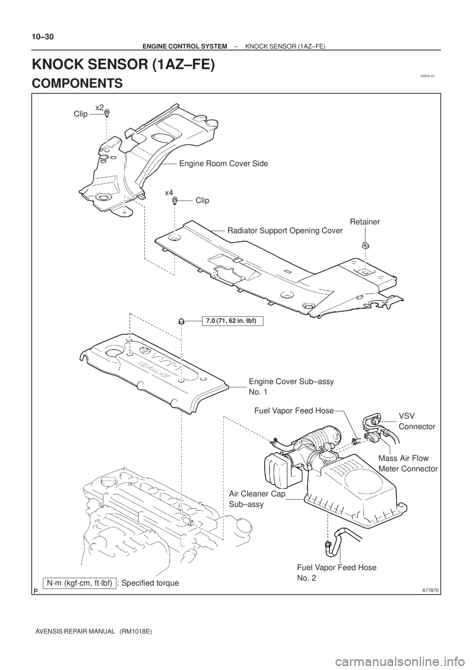
100FK±01
A77870
Mass Air Flow
Meter Connector
N´m (kgf´cm, ft´lbf) : Specified torqueEngine Cover Sub±assy
No. 1
7.0 (71, 62 in.�lbf)
Fuel Vapor Feed Hose
No. 2
Air Cleaner Cap
Sub±assyVSV
Connector Fuel Vapor Feed Hose
Clip
Engine Room Cover Side
Radiator Support Opening Cover
Clip
Retainer
x2
x4 10±30
± ENGINE CONTROL SYSTEMKNOCK SENSOR (1AZ±FE)
AVENSIS REPAIR MANUAL (RM1018E)
KNOCK SENSOR (1AZ±FE)
COMPONENTS
Page 245 of 1690

(b)
A77919
10±34
±
ENGINE CONTROL SYSTEM KNOCK SENSOR(1AZ±FE)
AVENSIS REPAIR MANUAL (RM1018E)
REPLACEMENT
1.DISCHARGE FUEL SYSTEM PRESSURE (See page 11±15)
2.REMOVE E")
100FL±01
A77917
A77918
(a)
(b)
A77919
10±34
±
ENGINE CONTROL SYSTEM KNOCK SENSOR(1AZ±FE)
AVENSIS REPAIR MANUAL (RM1018E)
REPLACEMENT
1.DISCHARGE FUEL SYSTEM PRESSURE (See page 11±15)
2.REMOVE ENGINE ROOM COVER SIDE (See page 10±26)
3.REMOVE RADIATOR SUPPORT OPENING COVER (See page 10±26)
4.ENGINE COOLANT (See page 16±19)
5.REMOVE ENGINE COVER SUB±ASSY NO.1 (See page 10±26)
6.REMOVE AIR CLEANER CAP SUB±ASSY (See page 10±26)
7.SEPARATE ACCELERATOR CONTROL CABLE ASSY (See page 10±26)
8.REMOVE THROTTLE BODY ASSY (See page 10±26)
9.DISCONNECT FUEL TUBE SUB±ASSY (See page 11±26) SST 09268±21010
10.REMOVE FUEL DELIVERY PIPE SUB±ASSY (See page 11±26)
11. REMOVE VARIABLE RESISTOR (LHD STEERINGPOSITION TYPE, LEADED GASOLINE)
(a) Disconnect the variable resistor connector.
(b) Remove the bolt, and then remove the variable resistor.
12. REMOVE CHARCOAL CANISTER ASSY
(a) Disconnect the charcoal canister outlet hose No. 1.
(b) Disconnect the fuel hose.
(c) Pull up and remove the charcoal canister.
13. DISCONNECT HEATER INLET WATER HOSE

15 (155, 11)
15 (155")

12±5
AVENSIS REPAIR MANUAL (RM1018E)
5. INSPECT FUEL TANK CAP ASSY
(a) Visually check if the cap or gasket is deformed or")