Page 1023 of 1690
650SY±01
I35230
±
LIGHTING FOG LAMP ASSY LH
65±23
AVENSIS REPAIR MANUAL (RM1018E)
ADJUSTMENT
1.PUT VEHICLE THESE CONDITIONS
(a)Tire inflation pressure is within the specified value. (See page 28±1)
(b) Start the engine.
2. ADJUST FOG LIGHT AIM
(a) The fog light aim can be adjusted by turning the aimingscrew in the vertical direction.
HINT:
The optical aim moves upward when turning the screwdriver
clockwise and moves downward when turning the screwdriver
center clockwise.
3. CHECK FOG LIGHT AIM
Page 1030 of 1690
650SV±01
I33423
V LH LineV RH LineV Line
Ground
H Line
± LIGHTINGHEADLAMP UNIT LH
65±19
AVENSIS REPAIR MANUAL (RM1018E)
ADJUSTMENT
1. HEADLIGHT AIM ONLY
HINT:
�Perform aiming adjustment with Low±beam.
�Since the Low±beam light and the High±beam light is a
unit, if aiming on either side is connect, the other side
should also be connect.
However, check both beams just to make sure.
(a) Prepare vehicle in the following conditions.
�Check that any damage or deformation does not exist on
the body around the headlights.
�Fuel tank is full.
�The tire inflation pressure is at the specified level.
�Vehicle is parked at a level surface.
�A person having an average weight sits in the driver's
seat.
�Vehicle is bounced up and down to stabilize the suspen-
sion to the normal position.
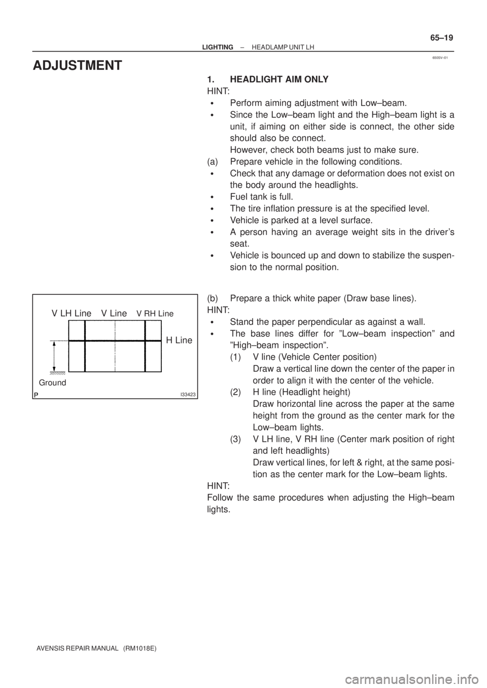
(b) Prepare a thick white paper (Draw base lines).
HINT:
�Stand the paper perpendicular as against a wall.
�The base lines differ for ºLow±beam inspectionº and
ºHigh±beam inspectionº.
(1) V line (Vehicle Center position)
Draw a vertical line down the center of the paper in
order to align it with the center of the vehicle.
(2) H line (Headlight height)
Draw horizontal line across the paper at the same
height from the ground as the center mark for the
Low±beam lights.
(3) V LH line, V RH line (Center mark position of right
and left headlights)
Draw vertical lines, for left & right, at the same posi-
tion as the center mark for the Low±beam lights.
HINT:
Follow the same procedures when adjusting the High±beam
lights.
Page 1141 of 1690
Z15500
Oil
ReservoirPS Vane
Pump
PS Gear
SST(s)
Open
Lock Position
F08858
±
POWER STEERING POWER STEERING SYSTEM
51±7
AVENSIS REPAIR MANUAL (RM1018E)
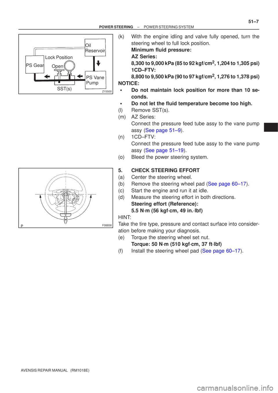
(k) With the engine idling and valve fully opened, turn the
steering wheel to full lock position.
Minimum fluid pressure:
AZ Series:
8,300 to 9,000 kPa (85 to 92 kgf/cm
2, 1,204 to 1,305 psi)
1CD±FTV:
8,800 to 9,500 kPa (90 to 97 kgf/cm
2, 1,276 to 1,378 psi)
NOTICE:
�Do not maintain lock position for more than 10 se-
conds.
�Do not let the fluid temperature become too high.
(l) Remove SST(s).
(m) AZ Series:
Connect the pressure feed tube assy to the vane pump
assy (See page 51±9).
(n) 1CD±FTV:
Connect the pressure feed tube assy to the vane pump
assy (See page 51±19).
(o) Bleed the power steering system.
5. CHECK STEERING EFFORT
(a) Center the steering wheel.
(b)Remove the steering wheel pad (See page 60±17).
(c) Start the engine and run it at idle.
(d) Measure the steering effort in both directions. Steering effort (Reference):
5.5 N´m (56 kgf´cm, 49 in.´lbf)
HINT:
Take the tire type, pressure and contact surface into consider-
ation before making your diagnosis.
(e) Torque the steering wheel set nut. Torque: 50 N´m (510 kgf´cm, 37 ft´lbf)
(f)Install the steering wheel pad (See page 60±17).
Page 1207 of 1690
02±16
± PREPARATIONENGINE MECHANICAL
AVENSIS REPAIR MANUAL (RM1018E) Vernier calipers
Tire pressure gauge
Alignment tester
Toe±in gauge
OBD II scan tool
Deep socket wrench 24 mm
Slide calipers
Sand paper (#400)
Wooden block
Chain block
Spark plug cleaner
Angle gauge
Universal engine lifter
SSM
08826±00080Seal Packing Black or equivalent
(FIPG)VALVE CLEARANCE(1AZ±FE)
CYLINDER HEAD GASKET(1AZ±FE)
VALVE CLEARANCE(1AZ±FSE)
CYLINDER HEAD
GASKET(1AZ±FSE)
VALVE CLEARANCE(1CD±FTV)
TIMING BELT(1CD±FTV)
CAMSHAFT(1CD±FTV)
CYLINDER HEAD
GASKET(1CD±FTV)
CRANKSHAFT SEAL(1CD±FTV)
PARTIAL ENGINE ASSY(1CD±FTV)
VA LV E
CLEARANCE(1ZZ±FE/3ZZ±FE)
CHAIN
SUB±ASSY(1ZZ±FE/3ZZ±FE)
CAMSHAFT(1ZZ±FE/3ZZ±FE)
CYLINDER HEAD
GASKET(1ZZ±FE/3ZZ±FE)
08833±00070ºAdhesive 1324,º
THREE BOND 1324 or equivalentPARTIAL ENGINE ASSY(1AZ±FE)
ENGINE REAR OIL SEAL(1AZ±FE)
PARTIAL ENGINE ASSY(1AZ±FSE)
ENGINE REAR OIL SEAL(1AZ±FSE)
ENGINE REAR OIL SEAL(1CD±FTV)
PARTIAL ENGINE ASSY(1CD±FTV)
PARTIAL ENGINE
ASSY(1ZZ±FE/3ZZ±FE)
ENGINE REAR OIL
SEAL(1ZZ±FE/3ZZ±FE)
Page 1210 of 1690
022KF±01
± PREPARATIONFRONT SUSPENSION
02±25
AVENSIS REPAIR MANUAL (RM1018E)
FRONT SUSPENSION
PREPARATION
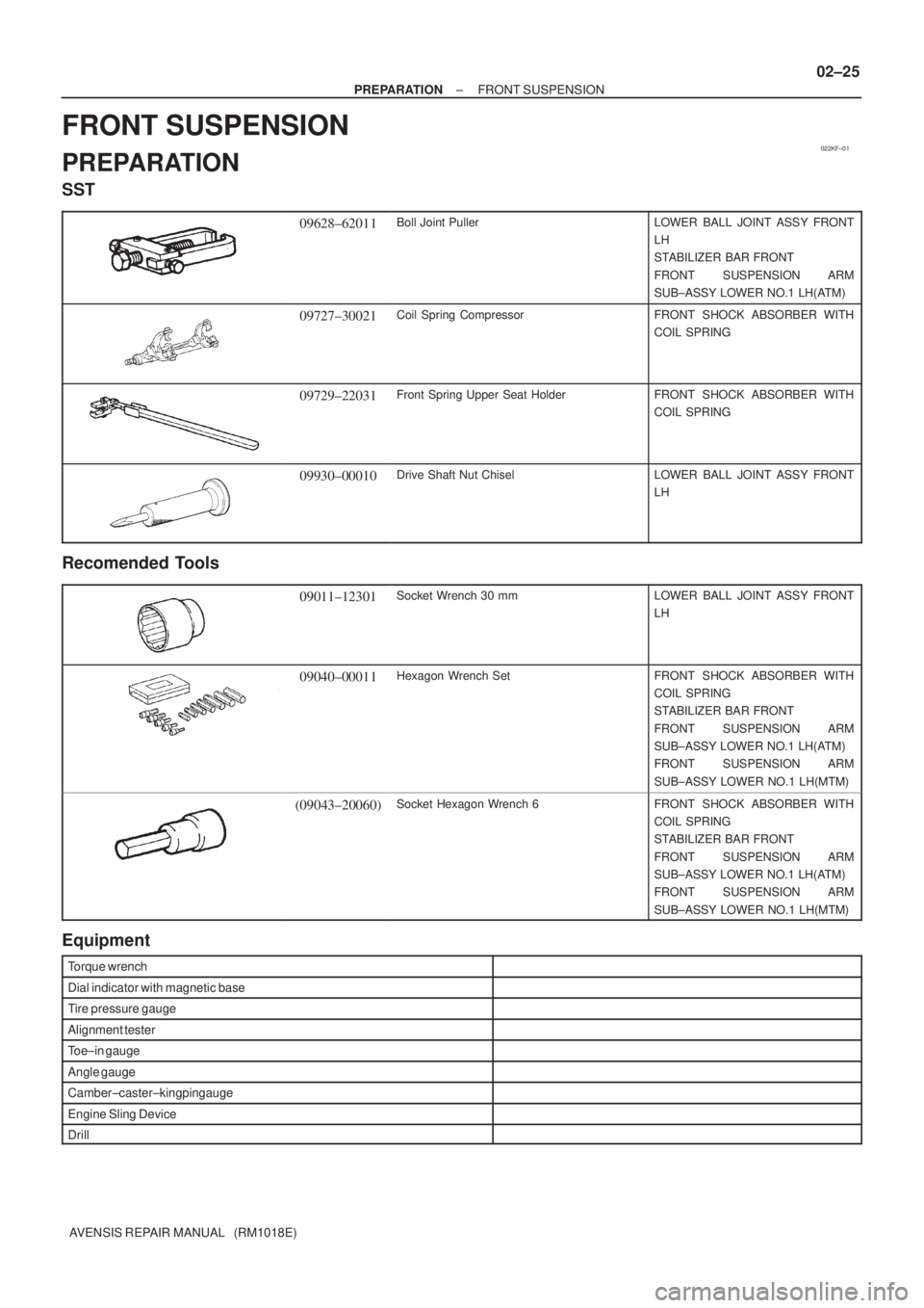
SST
09628±62011Boll Joint PullerLOWER BALL JOINT ASSY FRONT
LH
STABILIZER BAR FRONT
FRONT SUSPENSION ARM
SUB±ASSY LOWER NO.1 LH(ATM)
09727±30021Coil Spring CompressorFRONT SHOCK ABSORBER WITH
COIL SPRING
09729±22031Front Spring Upper Seat HolderFRONT SHOCK ABSORBER WITH
COIL SPRING
09930±00010Drive Shaft Nut ChiselLOWER BALL JOINT ASSY FRONT
LH
Recomended Tools
09011±12301Socket Wrench 30 mmLOWER BALL JOINT ASSY FRONT
LH
09040±00011Hexagon Wrench SetFRONT SHOCK ABSORBER WITH
COIL SPRING
STABILIZER BAR FRONT
FRONT SUSPENSION ARM
SUB±ASSY LOWER NO.1 LH(ATM)
FRONT SUSPENSION ARM
SUB±ASSY LOWER NO.1 LH(MTM)
(09043±20060)Socket Hexagon Wrench 6FRONT SHOCK ABSORBER WITH
COIL SPRING
STABILIZER BAR FRONT
FRONT SUSPENSION ARM
SUB±ASSY LOWER NO.1 LH(ATM)
FRONT SUSPENSION ARM
SUB±ASSY LOWER NO.1 LH(MTM)
Equipment
Torque wrench
Dial indicator with magnetic base
Tire pressure gauge
Alignment tester
Toe±in gauge
Angle gauge
Camber±caster±kingpin gauge
Engine Sling Device
Drill
Page 1232 of 1690
± PREPARATIONREAR SUSPENSION
02±27
AVENSIS REPAIR MANUAL (RM1018E)
(09955±04051)Claw No.5REAR SUSPENSION ARM ASSY
NO.1 LH
(09957±04010)AttachmentREAR SUSPENSION ARM ASSY
NO.1 LH
(09958±04011)HolderREAR SUSPENSION ARM ASSY
NO.1 LH
Recomended Tools
09040±00011Hexagon Wrench SetREAR SHOCK ABSORBER WITH
COIL SPRING
REAR SUSPENSION ARM ASSY
NO.1 LH
STABILIZER BAR REAR
(09043±20050)Socket Hexagon Wrench 5REAR SHOCK ABSORBER WITH
COIL SPRING
REAR SUSPENSION ARM ASSY
NO.1 LH
STABILIZER BAR REAR
(09043±20060)Socket Hexagon Wrench 6REAR SHOCK ABSORBER WITH
COIL SPRING
Equipment
Torque wrench
Dial indicator with magnetic base
Wheel balancer
Tire pressure gauge
Alignment tester
Toe±in gauge
Camber±caster±kingpin gauge
Drill
Page 1239 of 1690
022KG±01
02±28
± PREPARATIONTIRE & WHEEL
AVENSIS REPAIR MANUAL (RM1018E)
TIRE & WHEEL
PREPARATION
Equipment
Tire pressure gauge
Dial indicator with magnetic base
Wheel balancer
Page 1410 of 1690
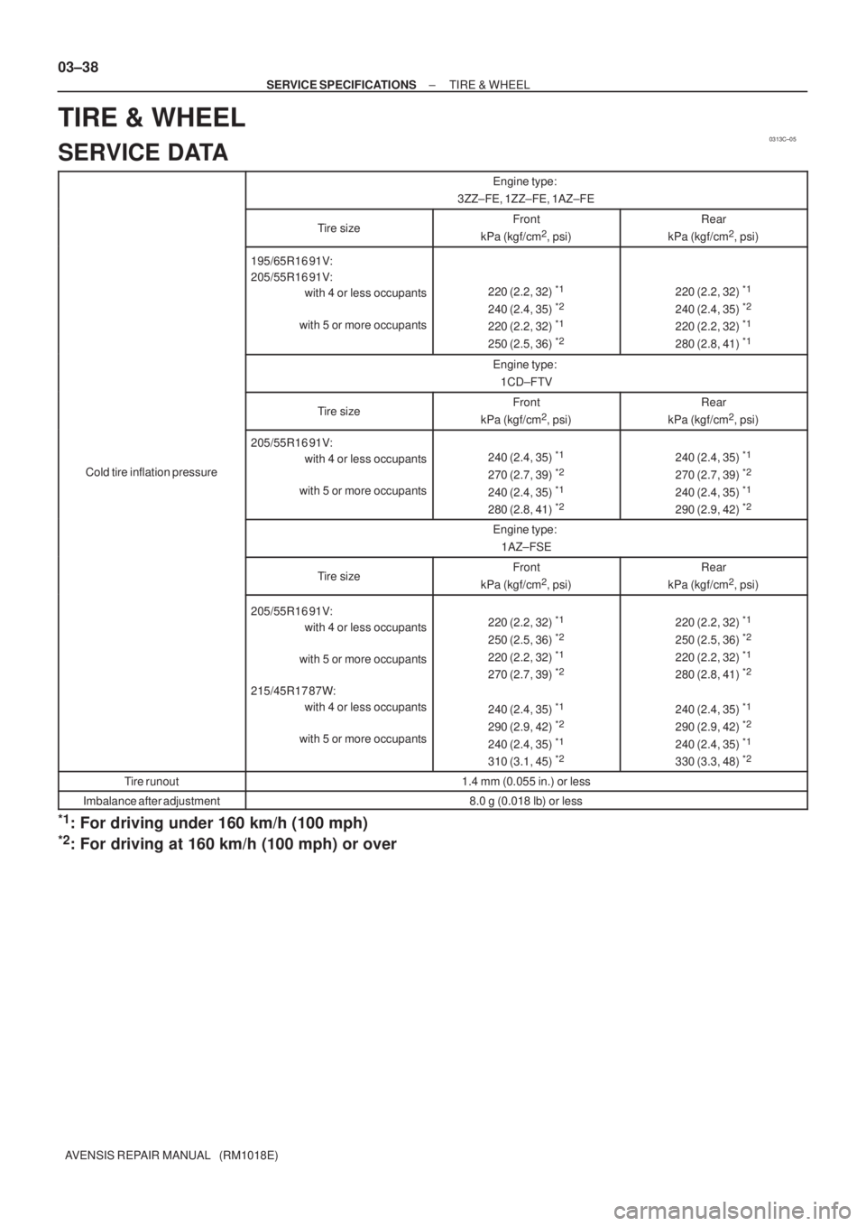
0313C±05
03±38
± SERVICE SPECIFICATIONSTIRE & WHEEL
AVENSIS REPAIR MANUAL (RM1018E)
TIRE & WHEEL
SERVICE DATA
Engine type:
3ZZ±FE, 1ZZ±FE, 1AZ±FE
Tire sizeFront
kPa (kgf/cm2, psi)
Rear
kPa (kgf/cm2, psi)
195/65R16 91V:
205/55R16 91V:
with 4 or less occupants
with 5 or more occupants
220 (2.2, 32) *1
240 (2.4, 35) *2
220 (2.2, 32) *1
250 (2.5, 36) *2
220 (2.2, 32) *1
240 (2.4, 35) *2
220 (2.2, 32) *1
280 (2.8, 41) *1
Engine type:
1CD±FTV
Tire sizeFront
kPa (kgf/cm2, psi)
Rear
kPa (kgf/cm2, psi)
Cold tire inflation pressure
205/55R16 91V:
with 4 or less occupants
with 5 or more occupants
240 (2.4, 35) *1
270 (2.7, 39) *2
240 (2.4, 35) *1
280 (2.8, 41) *2
240 (2.4, 35) *1
270 (2.7, 39) *2
240 (2.4, 35) *1
290 (2.9, 42) *2
Engine type:
1AZ±FSE
Tire sizeFront
kPa (kgf/cm2, psi)
Rear
kPa (kgf/cm2, psi)
205/55R16 91V:
with 4 or less occupants
with 5 or more occupants
215/45R17 87W:
with 4 or less occupants
with 5 or more occupants220 (2.2, 32) *1
250 (2.5, 36) *2
220 (2.2, 32) *1
270 (2.7, 39) *2
240 (2.4, 35) *1
290 (2.9, 42) *2
240 (2.4, 35) *1
310 (3.1, 45) *2
220 (2.2, 32) *1
250 (2.5, 36) *2
220 (2.2, 32) *1
280 (2.8, 41) *2
240 (2.4, 35) *1
290 (2.9, 42) *2
240 (2.4, 35) *1
330 (3.3, 48) *2
Tire runout1.4 mm (0.055 in.) or less
Imbalance after adjustment8.0 g (0.018 lb) or less
*1: For driving under 160 km/h (100 mph)
*2: For driving at 160 km/h (100 mph) or over