Page 56 of 1690
320W5±01
G24285
LHD Steering Position Type:
Charcoal Canister Assy
Brake Fluid Level
Switch Connector
Clutch Reservoir
Tube M/T Transaxle:Brake Booster Assy
Clip
Way
20 (204, 15)
15 (155, 11)
15 (155, 11)*1
29 (296, 21)*2
15 (155, 11)*1
29 (296, 21)*2
Brake Master
Cylinder Sub±assy
20 (204, 15)
Engin Room Relay Block
RHD Steering Position Type:Air Cleaner Cap Sub±assy
Brake Fluid Level
Switch ConnectorBrake Master
Cylinder Sub±assy
Clip
Accelerator Control
Cable Support
20 (204, 15)
*1
w/ ABS:*2 w/ VSC:N�m (kgf�cm, ft�lbf) : Specified torque
15 (155, 11)*1
29 (296, 21)*2
15 (155, 11)*1
29 (296, 21)*2
Clutch Reservoir
Tube M/T Transaxle:
Brake Booster Assy
5.4 (55, 48 in.�lbf)
Fuel Filter Assy Diesel Engin Type:
± BRAKEBRAKE MASTER CYLINDER SUB±ASSY
32±11
AVENSIS REPAIR MANUAL (RM1018E)
BRAKE MASTER CYLINDER SUB±ASSY
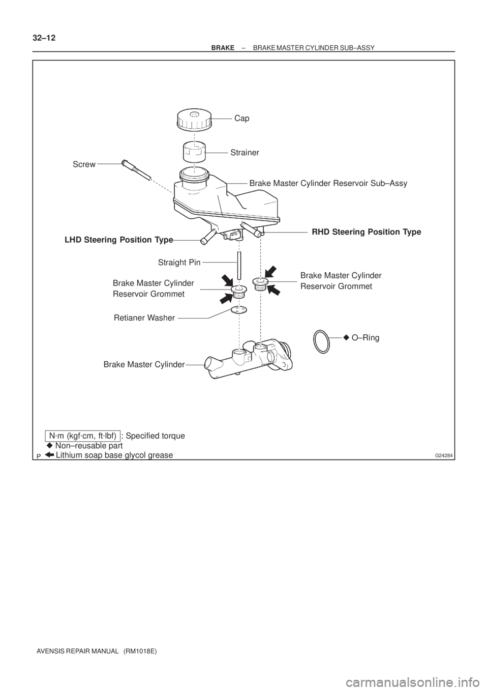
COMPONENTS
Page 57 of 1690
G24284
Cap
Strainer
Brake Master Cylinder Reservoir Sub±Assy
Brake Master Cylinder
Reservoir Grommet
Brake Master Cylinder
Straight Pin
Screw
Lithium soap base glycol grease � Non±reusable part
N�m (kgf�cm, ft�lbf) : Specified torque
Brake Master Cylinder
Reservoir Grommet LHD Steering Position TypeRHD Steering Position Type
� O±Ring
Retianer Washer
32±12
± BRAKEBRAKE MASTER CYLINDER SUB±ASSY
AVENSIS REPAIR MANUAL (RM1018E)
Page 58 of 1690

REPLACEMENT
NOTICE:
Do not adjust the brake booster push rod.
1. DRAIN BRAKE FLUID
NOTIC")
320W6±01
G24218
G24217
F45393
± BRAKEBRAKE MASTER CYLINDER SUB±ASSY
32±13
AVENSIS REPAIR MANUAL (RM1018E)
REPLACEMENT
NOTICE:
Do not adjust the brake booster push rod.
1. DRAIN BRAKE FLUID
NOTICE:
Wash the brake fluid off immediately if it adheres to any painted surface.
2. REMOVE ENGINE ROOM RELAY BLOCK (LHD STEERING POSITION TYPE)
3. REMOVE AIR CLEANER CAP SUB±ASSY (LHD STEERING POSITION TYPE)
4. REMOVE CHARCOAL CANISTER ASSY (LHD STEERING POSITION TYPE)
5. REMOVE FUEL FILTER ASSY (LHD STEERING POSITION TYPE)
(a) Diesal engine type:
Remove the fuel filter assy with the 3 bolts.
6. REMOVE BRAKE MASTER CYLINDER SUB±ASSY
(LHD STEERING POSITION TYPE)
(a) Disconnect the brake fluid level switch connector.
(b) M/T transaxle:
Slide the clip and disconnect the clutch reservoir tube.
(c) w/o VSC:
Using SST, disconnect the 2 brake lines from the brake
master cylinder sub±assy.
SST 09023±00100
(d) w/ VSC:
Using SST, disconnect the 2 brake lines from the brake
master cylinder sub±assy.
SST 09023±38400
(e) Using SST, disconnect the 2 brake lines from the way.
SST 09023±00100
(f) Remove the 2 nuts, and pull out the way and brake master
cylinder sub±assy.
(g) Remove the O±ring from the brake master cylinder sub±
assy.
Page 59 of 1690

7. REMOVE BRAKE MASTER CYLINDER SUB±ASSY")
G24225
F45394
F45395Lithium soap base glycol grease
Grommets
Retainer
Washer
32±14
± BRAKEBRAKE MASTER CYLINDER SUB±ASSY
AVENSIS REPAIR MANUAL (RM1018E)
7. REMOVE BRAKE MASTER CYLINDER SUB±ASSY
(RHD STEERING POSITION TYPE)
(a) Disconnect the brake fluid level switch connector.
(b) M/T transaxle:
Slide the clip and disconnect the clutch reservoir tube.
(c) w/o VSC:
Using SST, disconnect the 2 brake lines from the brake
master cylinder sub±assy.
SST 09023±00100
(d) w/ VSC:
Using SST, disconnect the 2 brake lines from the brake
master cylinder sub±assy.
SST 09023±38400
(e) Remove the 2 nuts and pull out the accelerator control
cable support and brake master cylinder sub±assy.
(f) Remove the O±ring from the brake master cylinder sub±
assy.
8. REMOVE BRAKE MASTER CYLINDER RESERVOIR SUB±ASSY
(a) Using a screwdriver, remove the screw from the brake master cylinder.
(b) Remove the brake master cylinder reservoir sub±assy and 2 brake master cylinder reservoir grommets
from the brake master cylinder.
(c) Remove the cap and strainer from the master cylinder reservoir.
9. INSTALL BRAKE MASTER CYLINDER RESERVOIR
SUB±ASSY
(a) Apply lithium soap base grycol grease to the 2 brake mas-
ter cylinder reservoir grommets.
(b) Install the retainer washer to the brake master cylinder.
(c) Install the 2 brake master cylinder reservoir grommets to
the brake master cylinder.
(d) Using a screwdriver, install the brake master cylinder re-
sevoir sub±assy with the screw.
Page 60 of 1690

10. INSTALL BRAKE MASTER CYLINDER SUB±ASSY
(LHD STEERING POSITION TYPE)
(a) Install the ne")
F45393
G24217
G24218
F45394
± BRAKEBRAKE MASTER CYLINDER SUB±ASSY
32±15
AVENSIS REPAIR MANUAL (RM1018E)
10. INSTALL BRAKE MASTER CYLINDER SUB±ASSY
(LHD STEERING POSITION TYPE)
(a) Install the new O±ring from the brake master cylinder
sub±assy.
(b) Install the brake master cylinder sub±assy and way
bracket with the 2 nuts.
Torque: 20 N�m (204 kgf�cm, 15 ft�lbf)
(c) Using SST, connect the 2 brake lines to the way.
SST 09023±00100
Torque: 15 N�m (155 kgf�cm, 11 ft�lbf)
(d) w/o VSC:
Using SST, connect the 2 brake lines to the brake master
cylinder sub±assy.
SST 09023±00100
Torque: 15 N�m (155 kgf�cm, 11 ft�lbf)
(e) w/ VSC:
Using SST, connect the 2 brake lines to the brake master
cylinder sub±assy.
SST 09023±38400
Torque: 29 N�m (296 kgf�cm, 21 ft�lbf)
(f) M/T transaxle:
Slide the clip and connect the clutch reservoir tube.
(g) Connect the brake fluid level switch connector.
11. INSTALL BRAKE MASTER CYLINDER SUB±ASSY
(RHD STEERING POSITION TYPE)
(a) Install the new O±ring from the brake master cylinder
sub±assy.
(b) Install the brake master cylinder sub±assy and accelera-
tor control cable support with the 2 nuts.
Torque: 20 N�m (204 kgf�cm, 15 ft�lbf)
Page 61 of 1690

(c) w/o VSC: Using SST, connect the 2 brake lines to the brake master
cylinder sub±assy.
SST 09023±00100
Torq")
G24225
32±16
±
BRAKE BRAKE MASTER CYLINDER SUB±ASSY
AVENSIS REPAIR MANUAL (RM1018E)
(c) w/o VSC: Using SST, connect the 2 brake lines to the brake master
cylinder sub±assy.
SST 09023±00100
Torque: 15 N �m (155 kgf �cm, 11 ft �lbf)
(d) w/ VSC: Using SST, connect the 2 brake lines to the brake master
cylinder sub±assy.
SST 09023±38400
Torque: 29 N �m (296 kgf �cm, 21 ft �lbf)
(e) M/T transaxle: Slide the clip and connect the clutch reservoir tube.
(f) Connect the brake fluid level switch connector.
12. INSTALL CHARCOAL CANISTER ASSY (LHD STEERING POSITION TYPE)
13. INSTALL ENGINE ROOM RELAY BLOCK (LHD STEERING POSITION TYPE)
14. INSTALL AIR CLEANER CAP SUB±ASSY (LHD STEERING POSITION TYPE)
15. INSTALL FUEL FILTER ASSY (LHD STEERING POSITION TYPE)
16.FILL RESERVOIR WITH BRAKE FLUID (See page 32±4)
17.BLEED MASTER CYLINDER (See page 32±4)
(a) w/o VSC: SST 09023±00100
(b) w/ VSC: SST 09023±38400
18.BLEED BRAKE LINE (See page 32±4)
19.BLEED CLUTCH PIPE LINE (M/T TRANSAXLE) (See page 42±13)
20.CHECK FLUID LEVEL IN RESERVOIR (See page 32±4)
21. CHECK BRAKE FLUID LEAKAGE
Page 87 of 1690

STEERING SENSOR
REPLACEMENT
1.PRECAUTION (See page 60±1)
2. REMOVE PLACE FRONT WHEELS FACING STRAIGHT")
320G5±02
F45426
F45427
F42642
±
BRAKE STEERING SENSOR
32±65
AVENSIS REPAIR MANUAL (RM1018E)
STEERING SENSOR
REPLACEMENT
1.PRECAUTION (See page 60±1)
2. REMOVE PLACE FRONT WHEELS FACING STRAIGHT AHEAD
3.DISCONNECT BATTERY NEGATIVE TERMINAL (See page 60±1)
4.REMOVE HORN BUTTON ASSY (See page 60±17)
5.REMOVE STEERING WHEEL ASSY (See page 50±9)
6.REMOVE STEERING COLUMN COVER LWR (See page 50±9)
7. REMOVE STEERING COLUMN COVER W/INSTRUMENT CLUSTER FINISH PANEL ASSY
(See page 50±9)
8.REMOVE STEERING COLUMN ASSY(See page 50±9)
9.REMOVE STEERING INTERMEDIATE SHAFT ASSY NO.2 (See page 50±9)
10. REMOVE STEERING SENSOR
(a) Place the steering column assy on the V±blocks and rub-ber stick.
(b) Using a extension bar and hammer, remove the steering column bracket spacer and 2 tilt steering support collar
No.1 from the steering column assy.
NOTICE:
�During this procedure, do not apply the strong shock
to the steering sensor.
�Do not apply any oil or grease on the pin.
(c) Using a screwdriver, remove the bush from the steering column assy.
(d) Disconnect the pick on the steering sensor and steering sensor adapter, then remove the steering sensor from the
column shaft.
(e) Remove the steering sensor adapter.
Page 88 of 1690

11. INSTALL STEERING SENSOR
(a) Install the steering sensor adapter to the column shaft.
HINT:
At that tim")
F42641
F42642
F45427
F45426
32±66
±
BRAKE STEERING SENSOR
AVENSIS REPAIR MANUAL (RM1018E)
11. INSTALL STEERING SENSOR
(a) Install the steering sensor adapter to the column shaft.
HINT:
At that time, the projection of the steering sensor adapter
should be fit in the hole on the steering column shaft.
(b) Install the steering sensor to the column shaft.
HINT:
�At that time, the pick of the steering sensor should be fit
to the pick of the steering sensor adapter.
�After installation, make sure the steering sensor is fixed
securely in the steering sensor adapter.
(c) Place the steering column assy on the V±blocks and rub- ber stick.
(d) Install the 2 new tilt steering support collar No.1 to the steering column assy.
(e) Using a extension bar and hammer, install the steering column bracket spacer to the steering column assy.
NOTICE:
�During this procedure, do not apply the strong shock
to the steering sensor.
�Do not apply any grease or oil on the pin.
12.INSTALL STEERING INTERMEDIATE SHAFT ASSY NO.2 (See page 50±9)
13.INSTALL STEERING COLUMN ASSY (See page 50±9)
14.INSTALL SPIRAL CABLE SUB±ASSY (See page 60±26)
15. INSTALL STEERING COLUMN COVER W/INSTRUMENT CLUSTER FINISH PANEL ASSY (See page 50±9)
16.INSTALL STEERING COLUMN COVER LWR (See page 50±9)
17.INSTALL STEERING WHEEL ASSY (See page 50±9)
18. INSPECT STEERING WHEEL CENTER POINT
19.INSTALL HORN BUTTON ASSY (See page 60±17)

15 (155, 11)
15 (155")