Page 244 of 1690
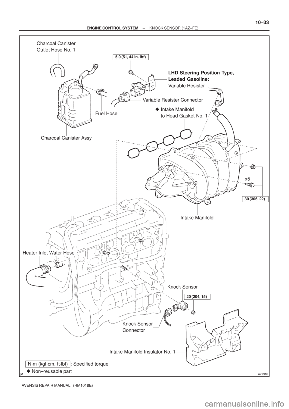
A77916� Non±reusable part
N´m (kgf´cm, ft´lbf) : Specified torque
30 (306, 22)
Heater Inlet Water Hose
Knock Sensor
ConnectorKnock Sensor
20 (204, 15)
Intake Manifold Insulator No. 1
� Intake Manifold
to Head Gasket No. 1
Intake Manifold
LHD Steering Position Type,
Leaded Gasoline:
Variable Resister
5.0 (51, 44 in.�lbf)
Charcoal Canister Assy
Variable Resister Connector
Charcoal Canister
Outlet Hose No. 1
Fuel Hose
x5
± ENGINE CONTROL SYSTEMKNOCK SENSOR (1AZ±FE)
10±33
AVENSIS REPAIR MANUAL (RM1018E)
Page 245 of 1690
100FL±01
A77917
A77918
(a)
(b)
A77919
10±34
±
ENGINE CONTROL SYSTEM KNOCK SENSOR(1AZ±FE)
AVENSIS REPAIR MANUAL (RM1018E)
REPLACEMENT
1.DISCHARGE FUEL SYSTEM PRESSURE (See page 11±15)
2.REMOVE ENGINE ROOM COVER SIDE (See page 10±26)
3.REMOVE RADIATOR SUPPORT OPENING COVER (See page 10±26)
4.ENGINE COOLANT (See page 16±19)
5.REMOVE ENGINE COVER SUB±ASSY NO.1 (See page 10±26)
6.REMOVE AIR CLEANER CAP SUB±ASSY (See page 10±26)
7.SEPARATE ACCELERATOR CONTROL CABLE ASSY (See page 10±26)
8.REMOVE THROTTLE BODY ASSY (See page 10±26)
9.DISCONNECT FUEL TUBE SUB±ASSY (See page 11±26) SST 09268±21010
10.REMOVE FUEL DELIVERY PIPE SUB±ASSY (See page 11±26)
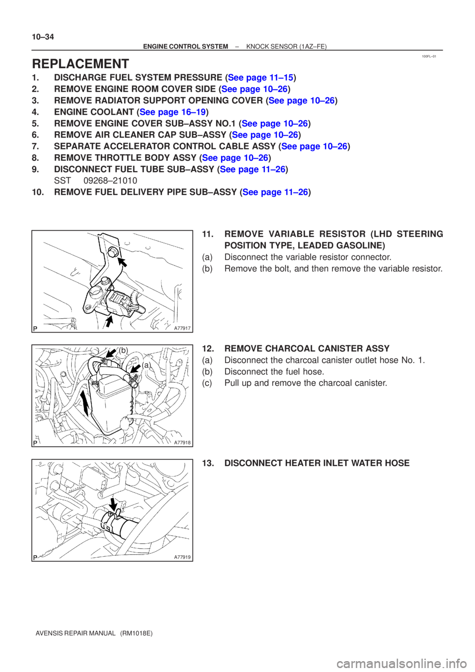
11. REMOVE VARIABLE RESISTOR (LHD STEERINGPOSITION TYPE, LEADED GASOLINE)
(a) Disconnect the variable resistor connector.
(b) Remove the bolt, and then remove the variable resistor.
12. REMOVE CHARCOAL CANISTER ASSY
(a) Disconnect the charcoal canister outlet hose No. 1.
(b) Disconnect the fuel hose.
(c) Pull up and remove the charcoal canister.
13. DISCONNECT HEATER INLET WATER HOSE
Page 247 of 1690

10±36
±
ENGINE CONTROL SYSTEM KNOCK SENSOR(1AZ±FE)
AVENSIS REPAIR MANUAL (RM1018E)
18.INSTALL INTAKE MANIFOLD INSULATOR NO.1
19.INSTALL INTAKE MANIFOLD
(a)Install a new gasket to the intake manifold.
(b)Install the intake manifold with the 5 bolts and 2 nuts. Torque: 30 N �m (306 kgf �cm, 22 ft �lbf)
(c)Install the wire harness clamp.
(d)Connect the union to connector tube hose.
20.CONNECT HEATER INLET WATER HOSE
21.INSTALL CHARCOAL CANISTER ASSY
22.INSTALL VARIABLE RESISTOR (LHD STEERING POSITION TYPE, LEADED GASOLINE) Torque: 5.0 N �m (51 kgf �cm, 44 in. �lbf)
23.INSTALL FUEL DELIVERY PIPE SUB±ASSY (See page 11±26)
24.CONNECT FUEL TUBE SUB±ASSY (See page 11±26)
25.INSTALL THROTTLE BODY ASSY (See page 10±26)
26.INSTALL ACCELERATOR CONTROL CABLE ASSY (See page 10±26)
27. INSTALL AIR CLEANER CAP SUB±ASSY
28.ADD ENGINE COOLANT (See page 16±19)
29.CHECK FOR ENGINE COOLANT LEAKS (See page 16±13)
30.CHECK FOR FUEL LEAKS (See page 11±19)
31.INSTALL ENGINE COVER SUB±ASSY NO.1 (See page 10±26)
32. INSTALL ENGINE ROOM COVER SIDE
33. INSTALL RADIATOR SUPPORT OPENING COVER
Page 251 of 1690
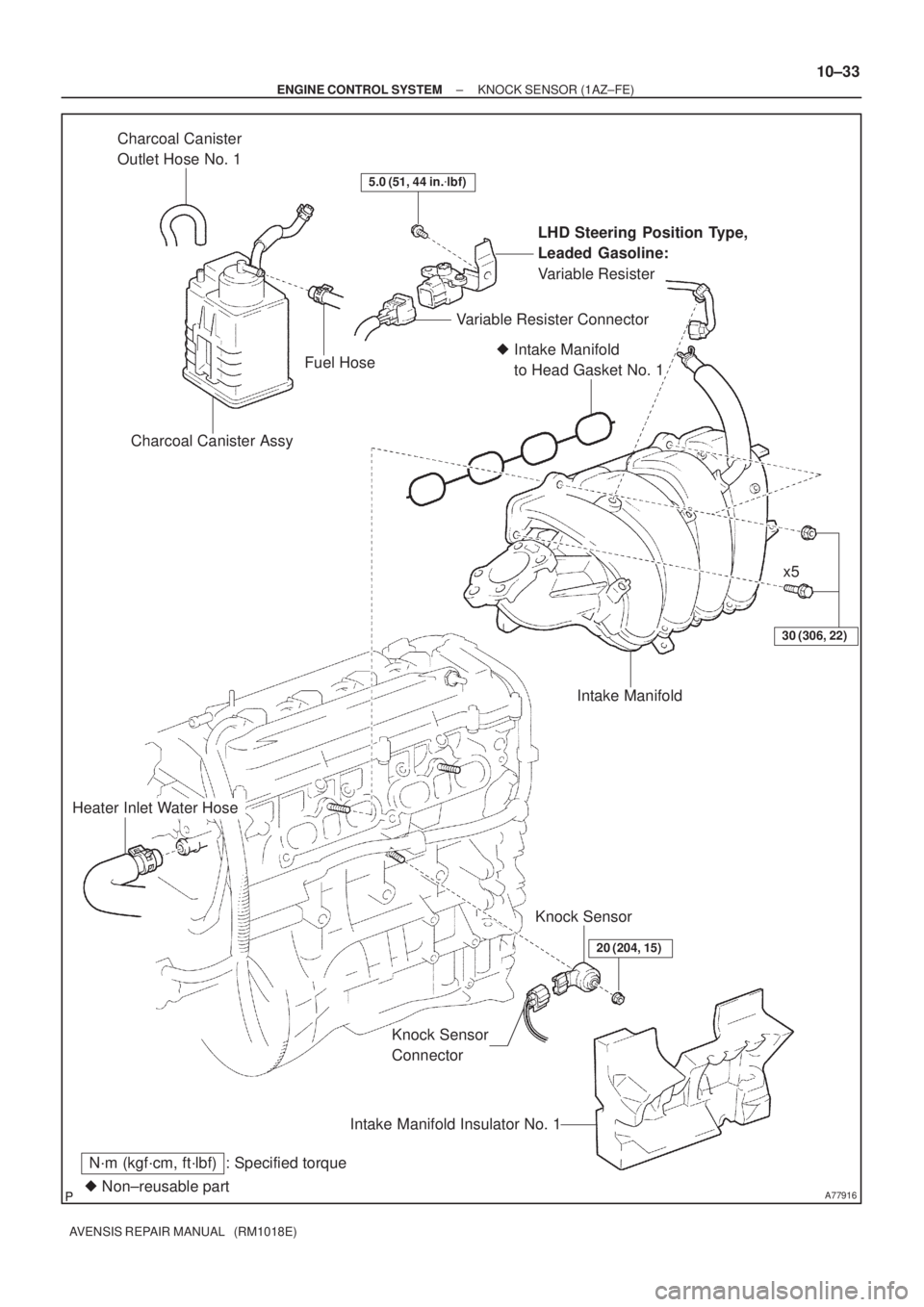
A77916� Non±reusable part
N´m (kgf´cm, ft´lbf) : Specified torque
30 (306, 22)
Heater Inlet Water Hose
Knock Sensor
ConnectorKnock Sensor
20 (204, 15)
Intake Manifold Insulator No. 1
� Intake Manifold
to Head Gasket No. 1
Intake Manifold
LHD Steering Position Type,
Leaded Gasoline:
Variable Resister
5.0 (51, 44 in.�lbf)
Charcoal Canister Assy
Variable Resister Connector
Charcoal Canister
Outlet Hose No. 1
Fuel Hose
x5
± ENGINE CONTROL SYSTEMKNOCK SENSOR (1AZ±FE)
10±33
AVENSIS REPAIR MANUAL (RM1018E)
Page 252 of 1690
100FL±01
A77917
A77918
(a)
(b)
A77919
10±34
±
ENGINE CONTROL SYSTEM KNOCK SENSOR(1AZ±FE)
AVENSIS REPAIR MANUAL (RM1018E)
REPLACEMENT
1.DISCHARGE FUEL SYSTEM PRESSURE (See page 11±15)
2.REMOVE ENGINE ROOM COVER SIDE (See page 10±26)
3.REMOVE RADIATOR SUPPORT OPENING COVER (See page 10±26)
4.ENGINE COOLANT (See page 16±19)
5.REMOVE ENGINE COVER SUB±ASSY NO.1 (See page 10±26)
6.REMOVE AIR CLEANER CAP SUB±ASSY (See page 10±26)
7.SEPARATE ACCELERATOR CONTROL CABLE ASSY (See page 10±26)
8.REMOVE THROTTLE BODY ASSY (See page 10±26)
9.DISCONNECT FUEL TUBE SUB±ASSY (See page 11±26) SST 09268±21010
10.REMOVE FUEL DELIVERY PIPE SUB±ASSY (See page 11±26)
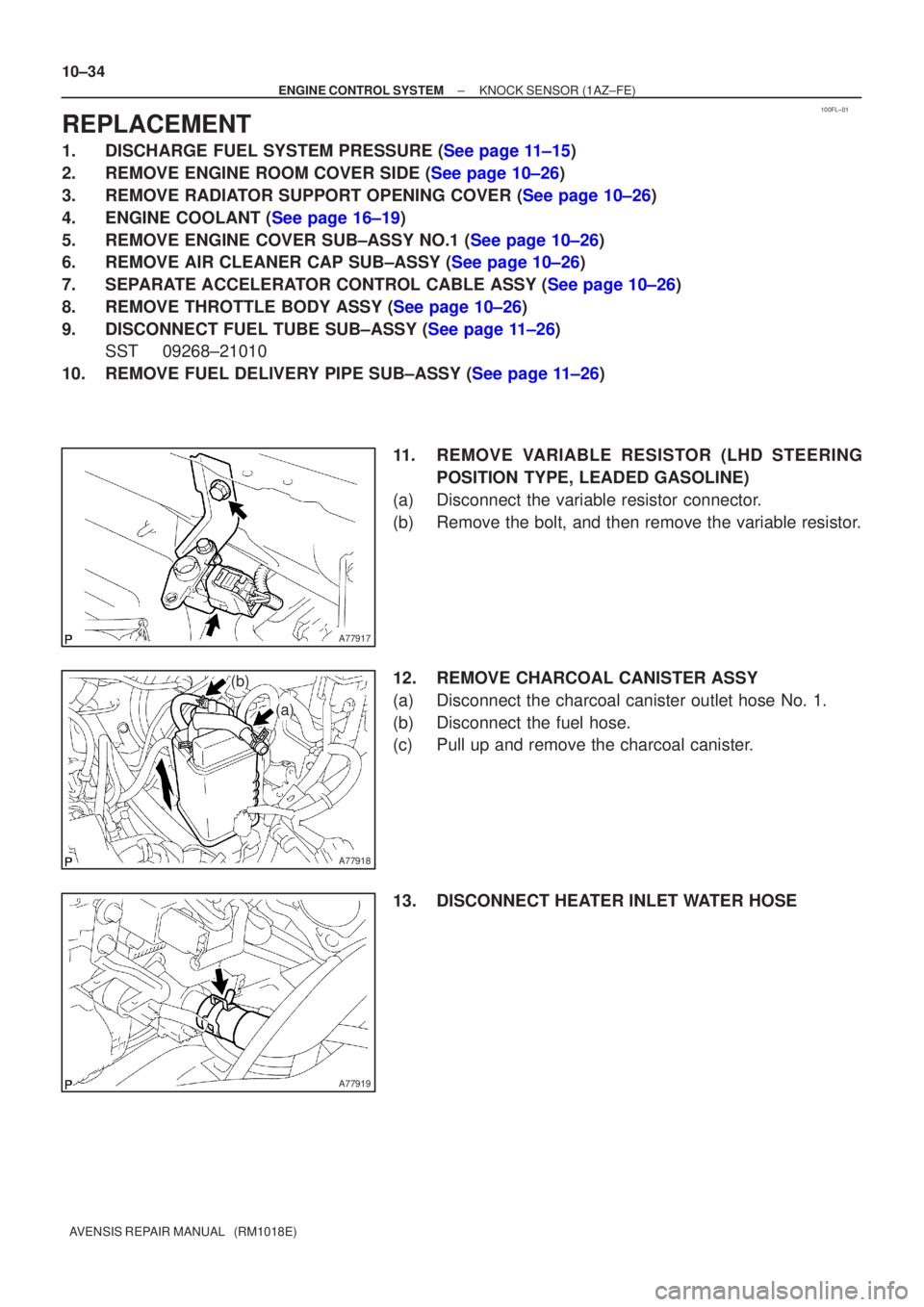
11. REMOVE VARIABLE RESISTOR (LHD STEERINGPOSITION TYPE, LEADED GASOLINE)
(a) Disconnect the variable resistor connector.
(b) Remove the bolt, and then remove the variable resistor.
12. REMOVE CHARCOAL CANISTER ASSY
(a) Disconnect the charcoal canister outlet hose No. 1.
(b) Disconnect the fuel hose.
(c) Pull up and remove the charcoal canister.
13. DISCONNECT HEATER INLET WATER HOSE
Page 254 of 1690
10±36
±
ENGINE CONTROL SYSTEM KNOCK SENSOR(1AZ±FE)
AVENSIS REPAIR MANUAL (RM1018E)
18.INSTALL INTAKE MANIFOLD INSULATOR NO.1
19.INSTALL INTAKE MANIFOLD
(a)Install a new gasket to the intake manifold.
(b)Install the intake manifold with the 5 bolts and 2 nuts. Torque: 30 N �m (306 kgf �cm, 22 ft �lbf)
(c)Install the wire harness clamp.
(d)Connect the union to connector tube hose.
20.CONNECT HEATER INLET WATER HOSE
21.INSTALL CHARCOAL CANISTER ASSY
22.INSTALL VARIABLE RESISTOR (LHD STEERING POSITION TYPE, LEADED GASOLINE) Torque: 5.0 N �m (51 kgf �cm, 44 in. �lbf)
23.INSTALL FUEL DELIVERY PIPE SUB±ASSY (See page 11±26)
24.CONNECT FUEL TUBE SUB±ASSY (See page 11±26)
25.INSTALL THROTTLE BODY ASSY (See page 10±26)
26.INSTALL ACCELERATOR CONTROL CABLE ASSY (See page 10±26)
27. INSTALL AIR CLEANER CAP SUB±ASSY
28.ADD ENGINE COOLANT (See page 16±19)
29.CHECK FOR ENGINE COOLANT LEAKS (See page 16±13)
30.CHECK FOR FUEL LEAKS (See page 11±19)
31.INSTALL ENGINE COVER SUB±ASSY NO.1 (See page 10±26)
32. INSTALL ENGINE ROOM COVER SIDE
33. INSTALL RADIATOR SUPPORT OPENING COVER
Page 267 of 1690
100G6±02
A75903
Air
A79035
VG
EVG
A79035E2
PSW
10±18
±
ENGINE CONTROL SYSTEM SFI SYSTEM(1AZ±FE)
AVENSIS REPAIR MANUAL (RM1018E)
SFI SYSTEM(1AZ±FE)
ON±VEHICLE INSPECTION
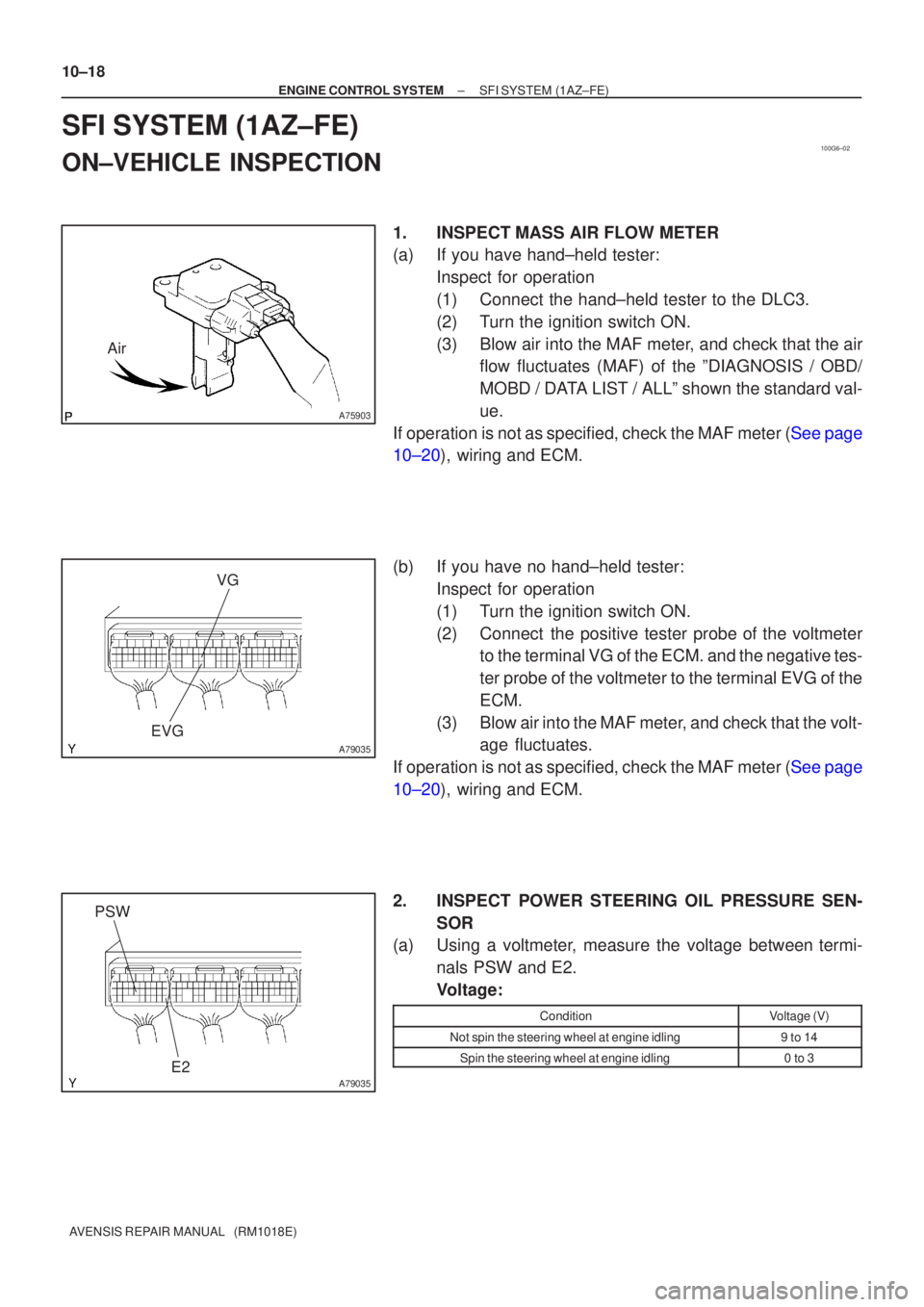
1.INSPECTMASS AIR FLOW METER
(a)If you have hand±held tester: Inspect for operation
(1)Connect the hand±held tester to the DLC3.
(2)Turn the ignition switch ON.
(3)Blow air into the MAF meter, and check that the airflow fluctuates (MAF) of the ºDIAGNOSIS / OBD/
MOBD / DATA LIST / ALLº shown the standard val-
ue.
If operation is not as specified, check the MAF meter (See page
10±20), wiring and ECM.
(b)If you have no hand±held tester: Inspect for operation
(1)Turn the ignition switch ON.
(2)Connect the positive tester probe of the voltmeterto the terminal VG of the ECM. and the negative tes-
ter probe of the voltmeter to the terminal EVG of the
ECM.
(3)Blow air into the MAF meter, and check that the volt- age fluctuates.
If operation is not as specified, check the MAF meter (See page
10±20), wiring and ECM.
2. INSPECT POWER STEERING OIL PRESSURE SEN- SOR
(a) Using a voltmeter, measure the voltage between termi-
nals PSW and E2.
Voltage:
ConditionVoltage (V)
Not spin the steering wheel at engine idling9 to 14
Spin the steering wheel at engine idling0 to 3
Page 273 of 1690
A53763
E2PSW
10±38
±
ENGINE CONTROL SYSTEM SFI SYSTEM(1AZ±FSE)
AVENSIS REPAIR MANUAL (RM1018E)
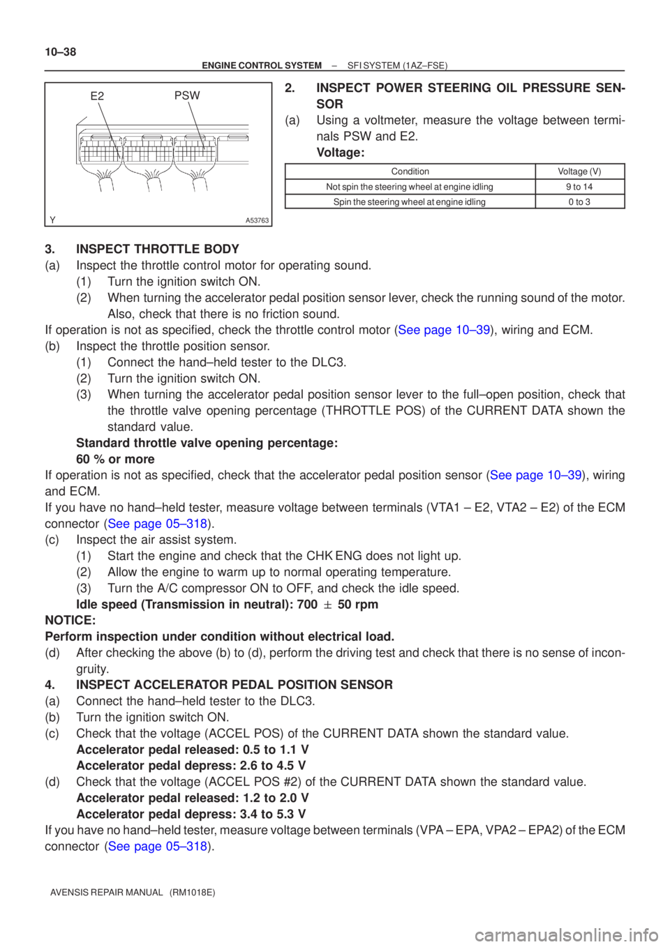
2.INSPECT POWER STEERING OIL PRESSURE SEN- SOR
(a)Using a voltmeter, measure the voltage between termi-
nals PSW and E2.
Voltage:
ConditionVoltage (V)
Not spin the steering wheel at engine idling9 to 14
Spin the steering wheel at engine idling0 to 3
3.INSPECT THROTTLE BODY
(a)Inspect the throttle control motor for operating sound.(1)Turn the ignition switch ON.
(2)When turning the accelerator pedal position sensor lever, check the running sound of the motor.Also, check that there is no friction sound.
If operation is not as specified, check the throttle control motor (See page 10±39), wiring and ECM.
(b) Inspect the throttle position sensor.
(1) Connect the hand±held tester to the DLC3.
(2) Turn the ignition switch ON.
(3) When turning the accelerator pedal position sensor lever to the full±\
open position, check thatthe throttle valve opening percentage (THROTTLE POS) of the CURRENT DATA shown the
standard value.
Standard throttle valve opening percentage:
60 % or more
If operation is not as specified, check that the accelerator pedal positio\
n sensor (See page 10±39), wiring
and ECM.
If you have no hand±held tester, measure voltage between terminals (VTA1 ± E2, VTA2 ± E2) of the ECM
connector (See page 05±318).
(c) Inspect the air assist system.
(1) Start the engine and check that the CHK ENG does not light up.
(2) Allow the engine to warm up to normal operating temperature.
(3) Turn the A/C compressor ON to OFF, and check the idle speed.
Idle speed (Transmission in neutral): 700 � 50 rpm
NOTICE:
Perform inspection under condition without electrical load.
(d) After checking the above (b) to (d), perform the driving test and check that there is no sense of incon-
gruity.
4. INSPECT ACCELERATOR PEDAL POSITION SENSOR
(a) Connect the hand±held tester to the DLC3.
(b) Turn the ignition switch ON.
(c) Check that the voltage (ACCEL POS) of the CURRENT DATA shown the standard value.
Accelerator pedal released: 0.5 to 1.1 V
Accelerator pedal depress: 2.6 to 4.5 V
(d) Check that the voltage (ACCEL POS #2) of the CURRENT DATA shown the standard value. Accelerator pedal released: 1.2 to 2.0 V
Accelerator pedal depress: 3.4 to 5.3 V
If you have no hand±held tester, measure voltage between terminals (VPA ± EPA, VPA2 ± EPA2) of the ECM
connector (See page 05±318).