Page 12 of 1690
670S4±01
± AUDIO & VISUAL SYSTEMAUDIO & VISUAL SYSTEM
67±1
AVENSIS REPAIR MANUAL (RM1018E)
AUDIO & VISUAL SYSTEM
PRECAUTION
1. OBSERVE HANDLING AND OPERATIONAL PRECAUTIONS
(a) Please explain to the customer that when the negative terminal is disconnected from the battery, the
channel information memory of the AM/FM broadcast stations in the radio receiver is cleared. If neces-
sary, make a note of the recorded channel information before the negative terminal is disconnected,
then reset the information after the negative terminal is reconnected.
(b) The removal/installation of the radio receiver should be performed after all the cassette tapes and au-
dio CDs are ejected from the radio receiver.
HINT:
If the cassette tapes and the audio CDs cannot be ejected due to the malfunction of the radio receiver, do
not try to drag them out by force. Bring the vehicle to the repair plant.
(c) Fasten the earth bolt securely when the antenna cord is removed or installed.
HINT:
Failing to fasten the earth bolt securely causes noise at the time of radio wave reception.
(d) Do not touch the cone paper of the speaker.
Page 239 of 1690
100FO±01
A80092
B08171
A64328
2 to 7 mm0 to 4 mm
± ENGINE CONTROL SYSTEMINTAKE SHUTTER ASSY (1CD±FTV)
10±61
AVENSIS REPAIR MANUAL (RM1018E)
Removal & Installation and Disassembly & Reassembly
1. REMOVE RADIATOR SUPPORT OPENING COVER
2. REMOVE ENGINE COVER NO.1
(a) Remove the 5 nuts and the engine cover.
3. REMOVE BATTERY
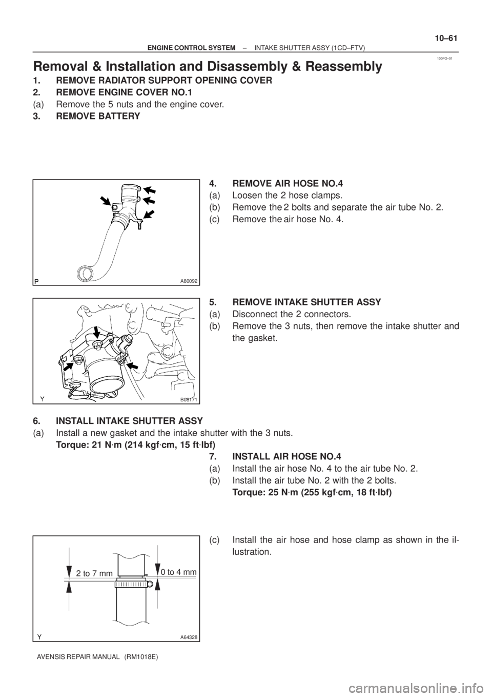
4. REMOVE AIR HOSE NO.4
(a) Loosen the 2 hose clamps.
(b) Remove the 2 bolts and separate the air tube No. 2.
(c) Remove the air hose No. 4.
5. REMOVE INTAKE SHUTTER ASSY
(a) Disconnect the 2 connectors.
(b) Remove the 3 nuts, then remove the intake shutter and
the gasket.
6. INSTALL INTAKE SHUTTER ASSY
(a) Install a new gasket and the intake shutter with the 3 nuts.
Torque: 21 N�m (214 kgf�cm, 15 ft�lbf)
7. INSTALL AIR HOSE NO.4
(a) Install the air hose No. 4 to the air tube No. 2.
(b) Install the air tube No. 2 with the 2 bolts.
Torque: 25 N�m (255 kgf�cm, 18 ft�lbf)
(c) Install the air hose and hose clamp as shown in the il-
lustration.
Page 282 of 1690
100FH±01
A778975 Claws
A77902
A77872
10±26
±
ENGINE CONTROL SYSTEM THROTTLE BODY ASSY(1AZ±FE)
AVENSIS REPAIR MANUAL (RM1018E)
Removal & Installation and Disassembly & Reassembly
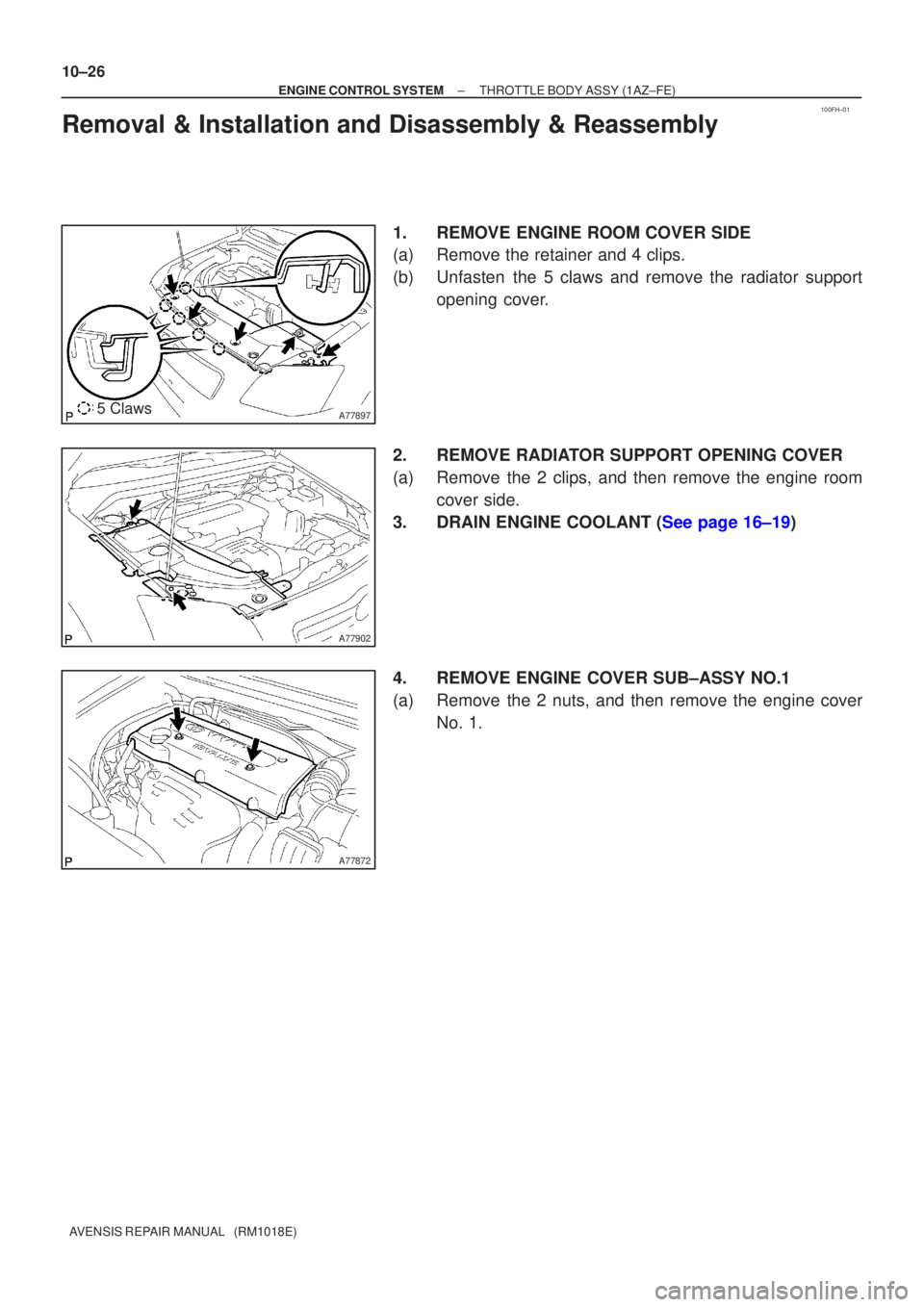
1.REMOVE ENGINE ROOM COVER SIDE
(a)Remove the retainer and 4 clips.
(b)Unfasten the 5 claws and remove the radiator support opening cover.
2.REMOVE RADIATOR SUPPORT OPENING COVER
(a)Remove the 2 clips, and then remove the engine room cover side.
3.DRAIN ENGINE COOLANT (See page 16±19)
4. REMOVE ENGINE COVER SUB±ASSY NO.1
(a) Remove the 2 nuts, and then remove the engine cover No. 1.
Page 293 of 1690
100FC±01
A784575 Claws
A78458
A78459
±
ENGINE CONTROL SYSTEM THROTTLE BODY ASSY(1ZZ±FE)
10±9
AVENSIS REPAIR MANUAL (RM1018E)
Removal & Installation and Disassembly & Reassembly
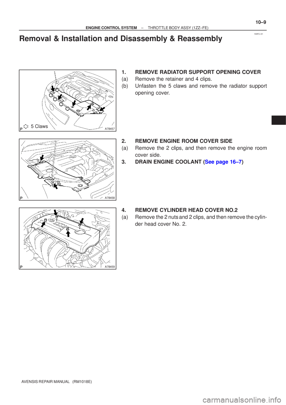
1.REMOVE RADIATOR SUPPORT OPENING COVER
(a)Remove the retainer and 4 clips.
(b)Unfasten the 5 claws and remove the radiator support
opening cover.
2.REMOVE ENGINE ROOM COVER SIDE
(a)Remove the 2 clips, and then remove the engine room cover side.
3.DRAIN ENGINE COOLANT (See page 16±7)
4. REMOVE CYLINDER HEAD COVER NO.2
(a) Remove the 2 nuts and 2 clips, and then remove the cylin- der head cover No. 2.
Page 299 of 1690
100FE±01
A78497
A78498
(a)
(b)
(c)
A78499
(d)
(e)
A78500
±
ENGINE CONTROL SYSTEM THROTTLE BODY ASSY(3ZZ±FE)
10±15
AVENSIS REPAIR MANUAL (RM1018E)
Removal & Installation and Disassembly & Reassembly
1.REMOVE RADIATOR SUPPORT OPENING COVER (See page 10±9)
2.REMOVE ENGINE ROOM COVER SIDE (See page 10±9)
3.DRAIN ENGINE COOLANT (See page 16±7)
4.REMOVE CYLINDER HEAD COVER NO.2 (See page 10±9)
5.REMOVE AIR CLEANER CAP SUB±ASSY (See page 10±9)
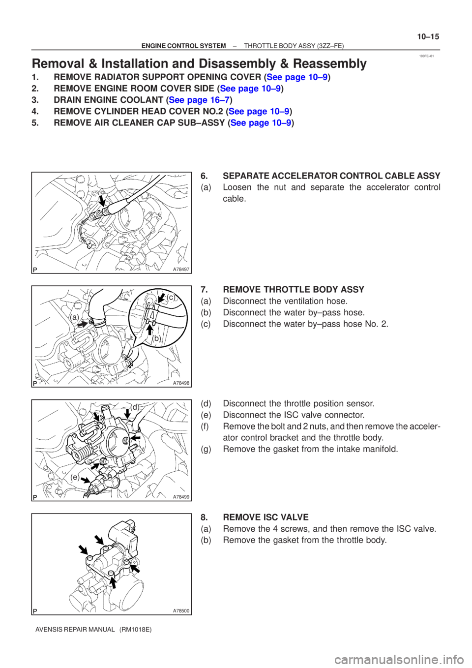
6. SEPARATE ACCELERATOR CONTROL CABLE ASSY
(a) Loosen the nut and separate the accelerator controlcable.
7. REMOVE THROTTLE BODY ASSY
(a) Disconnect the ventilation hose.
(b) Disconnect the water by±pass hose.
(c) Disconnect the water by±pass hose No. 2.
(d) Disconnect the throttle position sensor.
(e) Disconnect the ISC valve connector.
(f) Remove the bolt and 2 nuts, and then remove the acceler- ator control bracket and the throttle body.
(g) Remove the gasket from the intake manifold.
8. REMOVE ISC VALVE
(a) Remove the 4 screws, and then remove the ISC valve.
(b) Remove the gasket from the throttle body.
Page 304 of 1690
750N6±01
B66988: Clip
B66989: Clip
Hook
B66990: Clip
B66991
75±40
±
ENGINE HOOD/DOOR BACK DOOR(LIFTBACK MODELS)
AVENSIS REPAIR MANUAL (RM1018E)
OVERHAUL
HINT:
The installation is in the reverse order of the removal. However, when there is a special point concerning
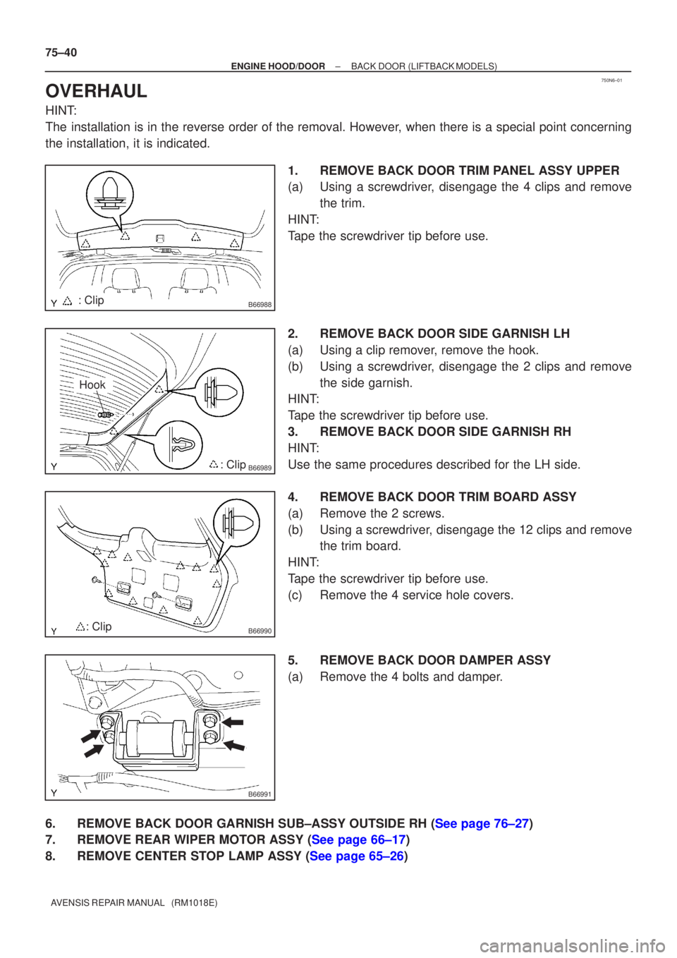
the installation, it is indicated. 1.REMOVE BACK DOOR TRIM PANEL ASSY UPPER
(a)Using a screwdriver, disengage the 4 clips and removethe trim.
HINT:
Tape the screwdriver tip before use.
2.REMOVE BACK DOOR SIDE GARNISH LH
(a)Using a clip remover, remove the hook.
(b)Using a screwdriver, disengage the 2 clips and remove the side garnish.
HINT:
Tape the screwdriver tip before use.
3.REMOVE BACK DOOR SIDE GARNISH RH
HINT:
Use the same procedures described for the LH side.
4.REMOVE BACK DOOR TRIM BOARD ASSY
(a)Remove the 2 screws.
(b)Using a screwdriver, disengage the 12 clips and remove the trim board.
HINT:
Tape the screwdriver tip before use.
(c)Remove the 4 service hole covers.
5.REMOVE BACK DOOR DAMPER ASSY
(a)Remove the 4 bolts and damper.
6.REMOVE BACK DOOR GARNISH SUB±ASSY OUTSIDE RH (See page 76±27)
7.REMOVE REAR WIPER MOTOR ASSY (See page 66±17)
8.REMOVE CENTER STOP LAMP ASSY (See page 65±26)
Page 309 of 1690
750N9±01
B66997: Clip
H19055Clip
B66998: Clip
������B68469: Clip
±
ENGINE HOOD/DOOR BACK DOOR(WAGON MODELS)
75±45
AVENSIS REPAIR MANUAL (RM1018E)
OVERHAUL
HINT:
The installation is in the reverse order of the removal. However, when there is a special point concerning
the installation, it is indicated.
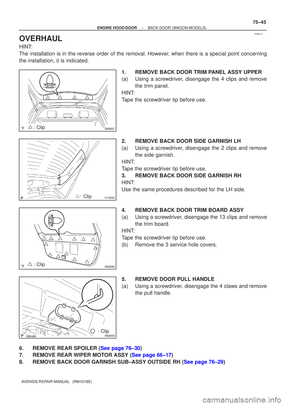
1.REMOVE BACK DOOR TRIM PANEL ASSY UPPER
(a)Using a screwdriver, disengage the 4 clips and removethe trim panel.
HINT:
Tape the screwdriver tip before use.
2.REMOVE BACK DOOR SIDE GARNISH LH
(a)Using a screwdriver, disengage the 2 clips and remove the side garnish.
HINT:
Tape the screwdriver tip before use.
3.REMOVE BACK DOOR SIDE GARNISH RH
HINT:
Use the same procedures described for the LH side.
4.REMOVE BACK DOOR TRIM BOARD ASSY
(a)Using a screwdriver, disengage the 13 clips and remove the trim board.
HINT:
Tape the screwdriver tip before use.
(b)Remove the 3 service hole covers.
5.REMOVE DOOR PULL HANDLE
(a)Using a screwdriver, disengage the 4 claws and remove the pull handle.
6.REMOVE REAR SPOILER (See page 76±30)
7.REMOVE REAR WIPER MOTOR ASSY (See page 66±17)
8.REMOVE BACK DOOR GARNISH SUB±ASSY OUTSIDE RH (See page 76±29)
Page 317 of 1690
750MX±01
B66969: Clip
B66970
: Clip
: Claw
B67801
Claw
75±8
±
ENGINE HOOD/DOOR FRONT DOOR
AVENSIS REPAIR MANUAL (RM1018E)
OVERHAUL
HINT:
�The installation is in the reverse order of the removal. However, when there is a special point concern-
ing the installation, it is indicated.
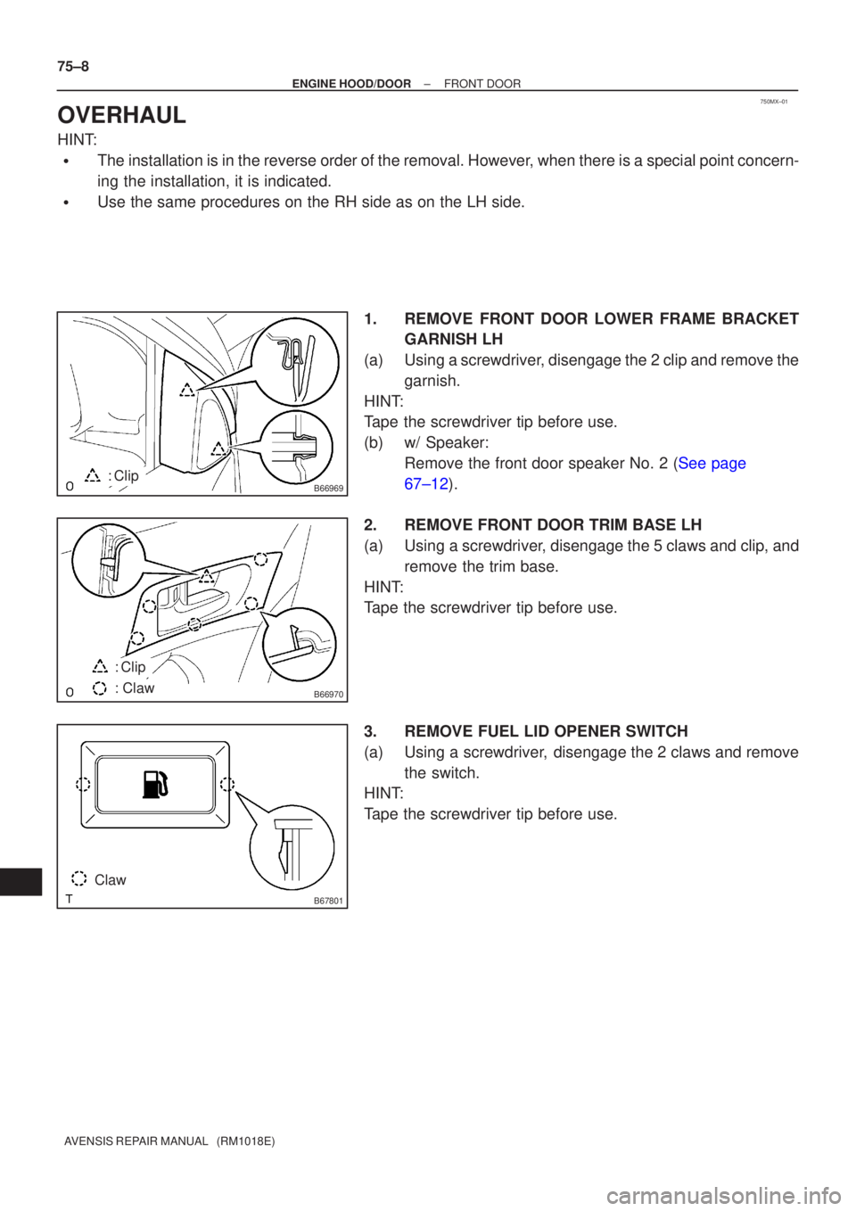
�Use the same procedures on the RH side as on the LH side. 1.REMOVE FRONT DOOR LOWER FRAME BRACKETGARNISH LH
(a)Using a screwdriver, disengage the 2 clip and remove the garnish.
HINT:
Tape the screwdriver tip before use.
(b)w/ Speaker: Remove the front door speaker No. 2 (See page
67±12).
2. REMOVE FRONT DOOR TRIM BASE LH
(a) Using a screwdriver, disengage the 5 claws and clip, and remove the trim base.
HINT:
Tape the screwdriver tip before use.
3. REMOVE FUEL LID OPENER SWITCH
(a) Using a screwdriver, disengage the 2 claws and remove the switch.
HINT:
Tape the screwdriver tip before use.