Page 15 of 1690
I35225
Navigation System:
Navigation Antenna Assy
Cigarette lighter Socket &
Retainer Assy
Cigarette lighter Knob
& Element Assy 67±4
± AUDIO & VISUAL SYSTEMAUDIO & VISUAL SYSTEM
AVENSIS REPAIR MANUAL (RM1018E)
Page 16 of 1690
670SJ±01
I35195
I35197Claw
I35196
I35205
±
AUDIO & VISUAL SYSTEM CIGARETTE LIGHTER ASSY
67±29
AVENSIS REPAIR MANUAL (RM1018E)
CIGARETTE LIGHTER ASSY
REPLACEMENT
1.REMOVE CONSOLE PANEL SUB±ASSY UPPER (See page 71±11)
2. REMOVE FRONT ASH RECEPTACLE ASSY
(a) Using a torx socket wrench (T20), remove the 4 screwsand front ash receptacle assy.
3. RE MO V E FRO NT AS H RE CE P TACLE RE TAINE R SUB±ASSY
(a) Disengage the claw and disconnect the connector.
(b) Push up the corner of the outer case open and remove the retainer assy as shown in the illustration.
4. REMOVE CIGARETTE LIGHTER ASSY
(a) Remove the 2 springs.
Page 17 of 1690
I351992 Claws
I35200
I35203
I35204
5.0mm
(0.20in.)
I35205
67±30
± AUDIO & VISUAL SYSTEMCIGARETTE LIGHTER ASSY
AVENSIS REPAIR MANUAL (RM1018E)
(b) Disengage the 2 claws and remove the door.
(c) Push out the cigarette lighter housing to the room side.
(d) Push out the cigarette lighter ring w/ wire harness to the
room side.
5. INSTALL CIGARETTE LIGHTER ASSY
(a) Align the claws of the cigarette lighter ring with the
notches of the cigarette lighter box to fix the cigarette
lighter w/ wire harness.
(b) Push the cigarette lighter housing to the out side.
(c) Install the wire harness as shown in the illustration.
(d) Place the wire harness in the position shown in the il-
lustration and install the door cover.
(e) Install the 2 springs.
Page 18 of 1690
I35206
I35195
± AUDIO & VISUAL SYSTEMCIGARETTE LIGHTER ASSY
67±31
AVENSIS REPAIR MANUAL (RM1018E)
(f) Make sure that the 2 springs are hooked on the claws and
install the retainer assy.
(g) Connect the connecter.
(h) Using a torx socket wrench (T20), install the 4 screws and
front ash receptacle.
Page 38 of 1690

3201G±07
BR2238
GOOD NO GOOD
2nd3rd
1st
BR2237
G24221
Ventilation No Ventilation
± BRAKEBRAKE BOOSTER ASSY (LHD)
32±17
AVENSIS REPAIR MANUAL (RM1018E)
BRAKE BOOSTER ASSY (LHD)
ON±VEHICLE INSPECTION
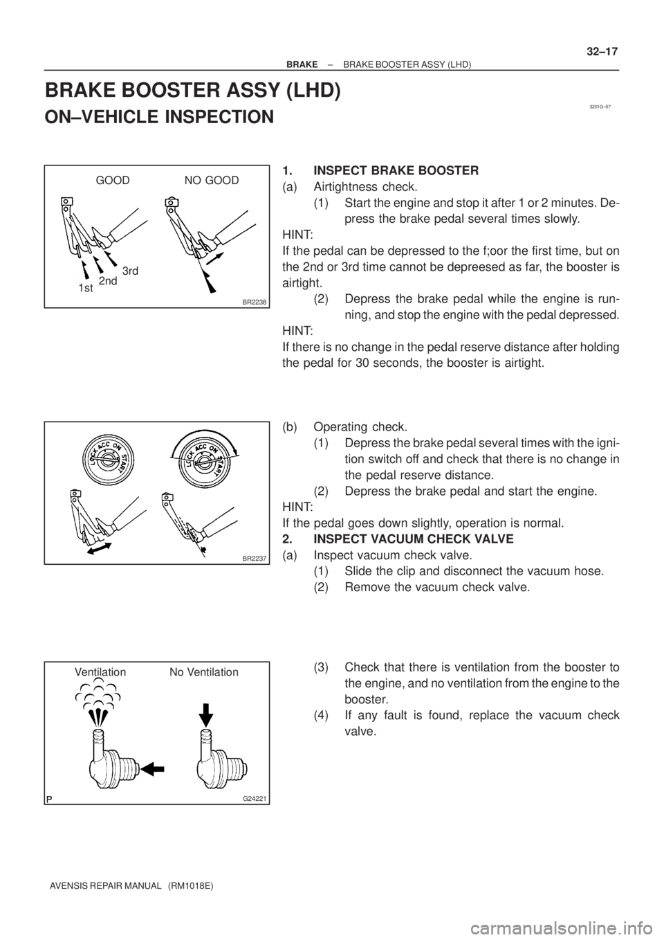
1. INSPECT BRAKE BOOSTER
(a) Airtightness check.
(1) Start the engine and stop it after 1 or 2 minutes. De-
press the brake pedal several times slowly.
HINT:
If the pedal can be depressed to the f;oor the first time, but on
the 2nd or 3rd time cannot be depreesed as far, the booster is
airtight.
(2) Depress the brake pedal while the engine is run-
ning, and stop the engine with the pedal depressed.
HINT:
If there is no change in the pedal reserve distance after holding
the pedal for 30 seconds, the booster is airtight.
(b) Operating check.
(1) Depress the brake pedal several times with the igni-
tion switch off and check that there is no change in
the pedal reserve distance.
(2) Depress the brake pedal and start the engine.
HINT:
If the pedal goes down slightly, operation is normal.
2. INSPECT VACUUM CHECK VALVE
(a) Inspect vacuum check valve.
(1) Slide the clip and disconnect the vacuum hose.
(2) Remove the vacuum check valve.
(3) Check that there is ventilation from the booster to
the engine, and no ventilation from the engine to the
booster.
(4) If any fault is found, replace the vacuum check
valve.
Page 42 of 1690

320GN±02
BR2238
GOOD NO GOOD
2nd3rd
1st
BR2237
G24221
Ventilation No Ventilation
± BRAKEBRAKE BOOSTER ASSY (RHD)
32±21
AVENSIS REPAIR MANUAL (RM1018E)
BRAKE BOOSTER ASSY (RHD)
ON±VEHICLE INSPECTION
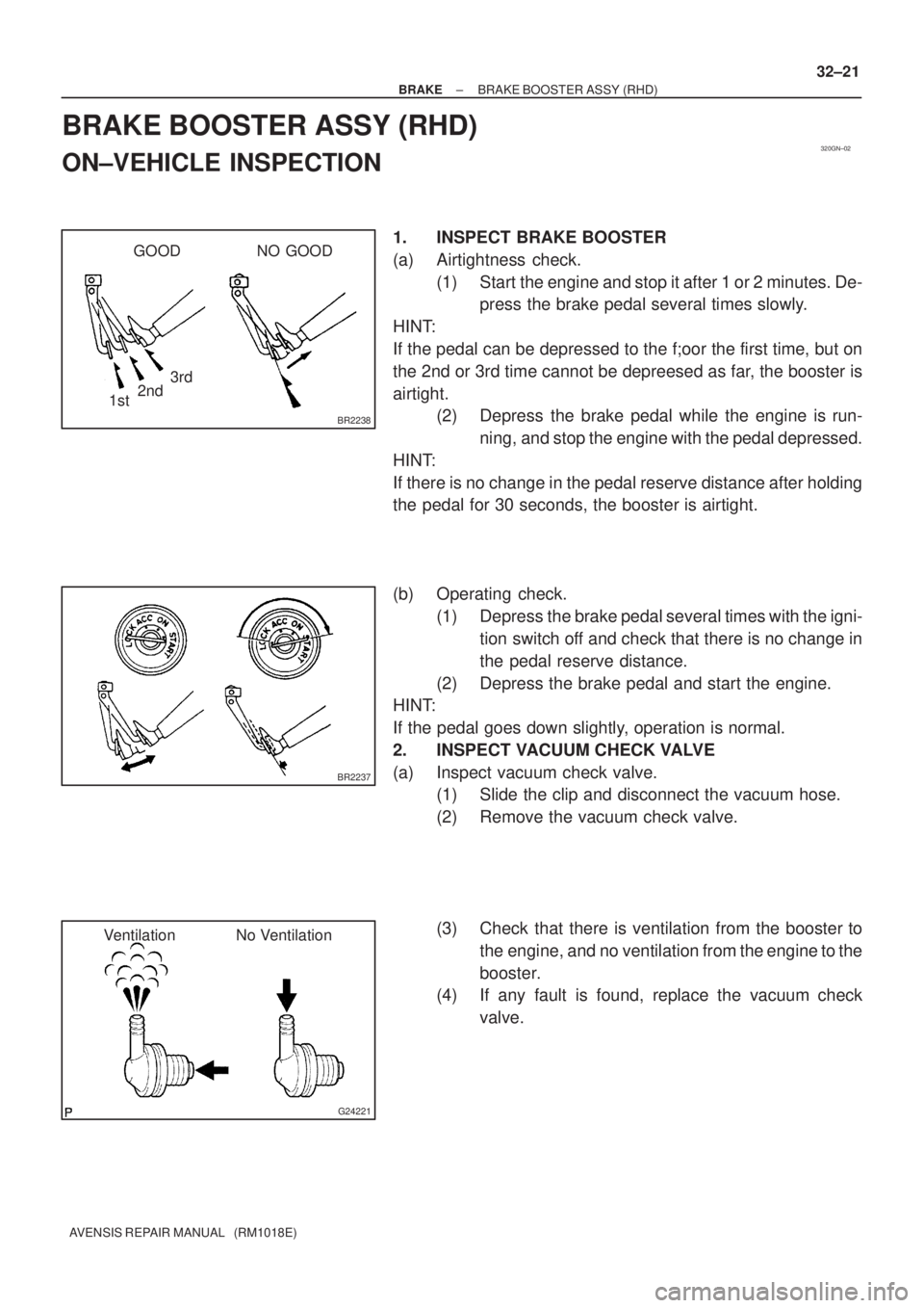
1. INSPECT BRAKE BOOSTER
(a) Airtightness check.
(1) Start the engine and stop it after 1 or 2 minutes. De-
press the brake pedal several times slowly.
HINT:
If the pedal can be depressed to the f;oor the first time, but on
the 2nd or 3rd time cannot be depreesed as far, the booster is
airtight.
(2) Depress the brake pedal while the engine is run-
ning, and stop the engine with the pedal depressed.
HINT:
If there is no change in the pedal reserve distance after holding
the pedal for 30 seconds, the booster is airtight.
(b) Operating check.
(1) Depress the brake pedal several times with the igni-
tion switch off and check that there is no change in
the pedal reserve distance.
(2) Depress the brake pedal and start the engine.
HINT:
If the pedal goes down slightly, operation is normal.
2. INSPECT VACUUM CHECK VALVE
(a) Inspect vacuum check valve.
(1) Slide the clip and disconnect the vacuum hose.
(2) Remove the vacuum check valve.
(3) Check that there is ventilation from the booster to
the engine, and no ventilation from the engine to the
booster.
(4) If any fault is found, replace the vacuum check
valve.
Page 89 of 1690
±
BRAKE STEERING SENSOR
32±67
AVENSIS REPAIR MANUAL (RM1018E)
20.CONNECT BATTERY NEGATIVE TERMINAL (See page 60±1)
21.INSPECT SRS WARNING LIGHT (See page 05±1184)
22.INSPECT ABS WARNING LIGHT AND VSC WARNING LIGHT (See page 05±756)
Page 128 of 1690

Q01060
D30059
1CD±FTV Engine Type: Others:
Flywheel Side
SST(s)
D26323
SST(s)
Matchmarks 7
1 (Temporally), 4
3
6
2.58
D00205
SST(s)
42±28
± CLUTCHCLUTCH UNIT (MTM)
AVENSIS REPAIR MANUAL (RM1018E)
12. INSPECT CLUTCH RELEASE BEARING ASSY
(a) Turn the release bearing by hand while applying force in
the axial direction.
HINT:
The bearing is permanently lubricated and requires no cleaning
or lubrication.
Replace the release bearing assy as necessary.
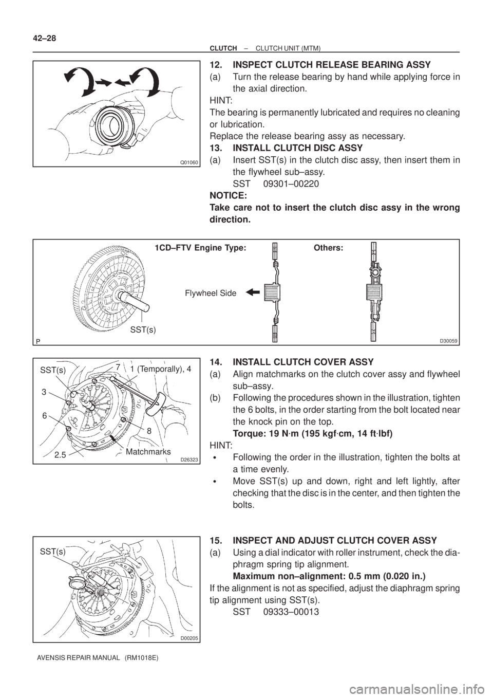
13. INSTALL CLUTCH DISC ASSY
(a) Insert SST(s) in the clutch disc assy, then insert them in
the flywheel sub±assy.
SST 09301±00220
NOTICE:
Take care not to insert the clutch disc assy in the wrong
direction.
14. INSTALL CLUTCH COVER ASSY
(a) Align matchmarks on the clutch cover assy and flywheel
sub±assy.
(b) Following the procedures shown in the illustration, tighten
the 6 bolts, in the order starting from the bolt located near
the knock pin on the top.
Torque: 19 N�m (195 kgf�cm, 14 ft�lbf)
HINT:
�Following the order in the illustration, tighten the bolts at
a time evenly.
�Move SST(s) up and down, right and left lightly, after
checking that the disc is in the center, and then tighten the
bolts.
15. INSPECT AND ADJUST CLUTCH COVER ASSY
(a) Using a dial indicator with roller instrument, check the dia-
phragm spring tip alignment.
Maximum non±alignment: 0.5 mm (0.020 in.)
If the alignment is not as specified, adjust the diaphragm spring
tip alignment using SST(s).
SST 09333±00013