Page 83 of 1690
320VV±01
G23167
F08657
BoltSST
SST
Bolt
±
BRAKE SKID CONTROL SENSOR
32±61
AVENSIS REPAIR MANUAL (RM1018E)
SKID CONTROL SENSOR
REPLACEMENT
HINT:
Replace the RH side by using the same procedures as those for the LH side.
1. REMOVE REAR WHEEL
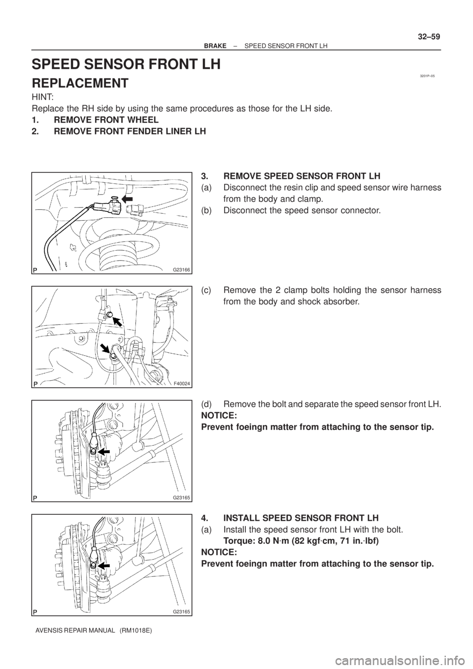
2. DISCONNECT SKID CONTROL SENSOR WIRE
(a) Disconnect the connector from the skid control sensor.
3. REMOVE REAR DISC BRAKE CALIPER ASSY LH
(a) Remove the 2 bolts and rear brake caliper assy LH.
4. REMOVE REAR DISC
(a) place matchmarks on the rear disc and the axle hub.
(b) Remove the rear disc.
5.REMOVE REAR AXLE HUB & BEARING ASSY LH (See page 30±31) 6. REMOVE SKID CONTROL SENSOR
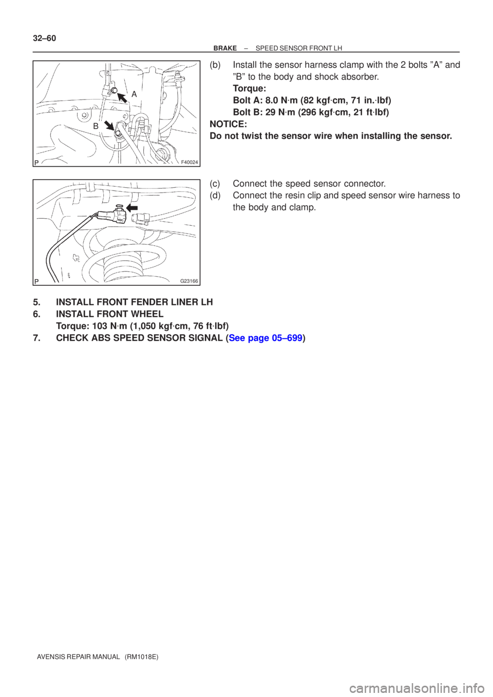
(a) Mount the rear axle hub in a soft jaw vise.
NOTICE:
Replace the axle hub assembly if it is dropped or receives
a strong shock.
(b) Using a pin punch and hammer, drive out the 2 pins andremove the 2 attachments from SST.
(c) Using SST and 2 bolts (Diameter: 12 mm, pitch: 1.5 mm), remove the skid control sensor from the rear axle hub.
SST 09520±00031 (09520±00040), 09521±00020, 09950±00020
NOTICE:
�If the sensor rotor is damaged, replace the axle hub
assembly.
�Do not scratch the contacting surface of the axle hub
and speed sensor.
Page 84 of 1690
G23168
F08658
SST
G23167
32±62
±
BRAKE SKID CONTROL SENSOR
AVENSIS REPAIR MANUAL (RM1018E)
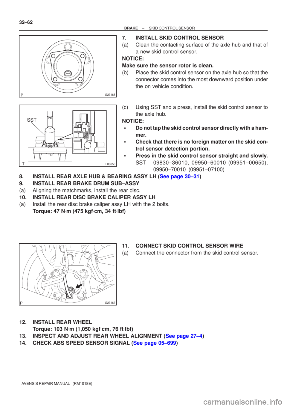
7. INSTALL SKID CONTROL SENSOR
(a) Clean the contacting surface of the axle hub and that of a new skid control sensor.
NOTICE:
Make sure the sensor rotor is clean.
(b) Place the skid control sensor on the axle hub so that the connector comes into the most downward position under
the on vehicle condition.
(c) Using SST and a press, install the skid control sensor to the axle hub.
NOTICE:
�Do not tap the skid control sensor directly with a ham-
mer.
�Check that there is no foreign matter on the skid con-
trol sensor detection portion.
�Press in the skid control sensor straight and slowly.
SST 09830±36010, 09950±60010 (09951±00650), 09950±70010 (09951±07100)
8.INSTALL REAR AXLE HUB & BEARING ASSY LH (See page 30±31)
9. INSTALL REAR BRAKE DRUM SUB±ASSY
(a) Aligning the matchmarks, install the rear disc.
10. INSTALL REAR DISC BRAKE CALIPER ASSY LH
(a) Install the rear disc brake caliper assy LH with the 2 bolts. Torque: 47 N �m (475 kgf �cm, 34 ft �lbf)
11. CONNECT SKID CONTROL SENSOR WIRE
(a) Connect the connector from the skid control sensor.
12. INSTALL REAR WHEEL Torque: 103 N �m (1,050 kgf �cm, 76 ft �lbf)
13.INSPECT AND ADJUST REAR WHEEL ALIGNMENT (See page 27±4)
14.CHECK ABS SPEED SENSOR SIGNAL (See page 05±699)
Page 85 of 1690
3201P±05
G23166
F40024
G23165
G23165
± BRAKESPEED SENSOR FRONT LH
32±59
AVENSIS REPAIR MANUAL (RM1018E)
SPEED SENSOR FRONT LH
REPLACEMENT
HINT:
Replace the RH side by using the same procedures as those for the LH side.
1. REMOVE FRONT WHEEL
2. REMOVE FRONT FENDER LINER LH
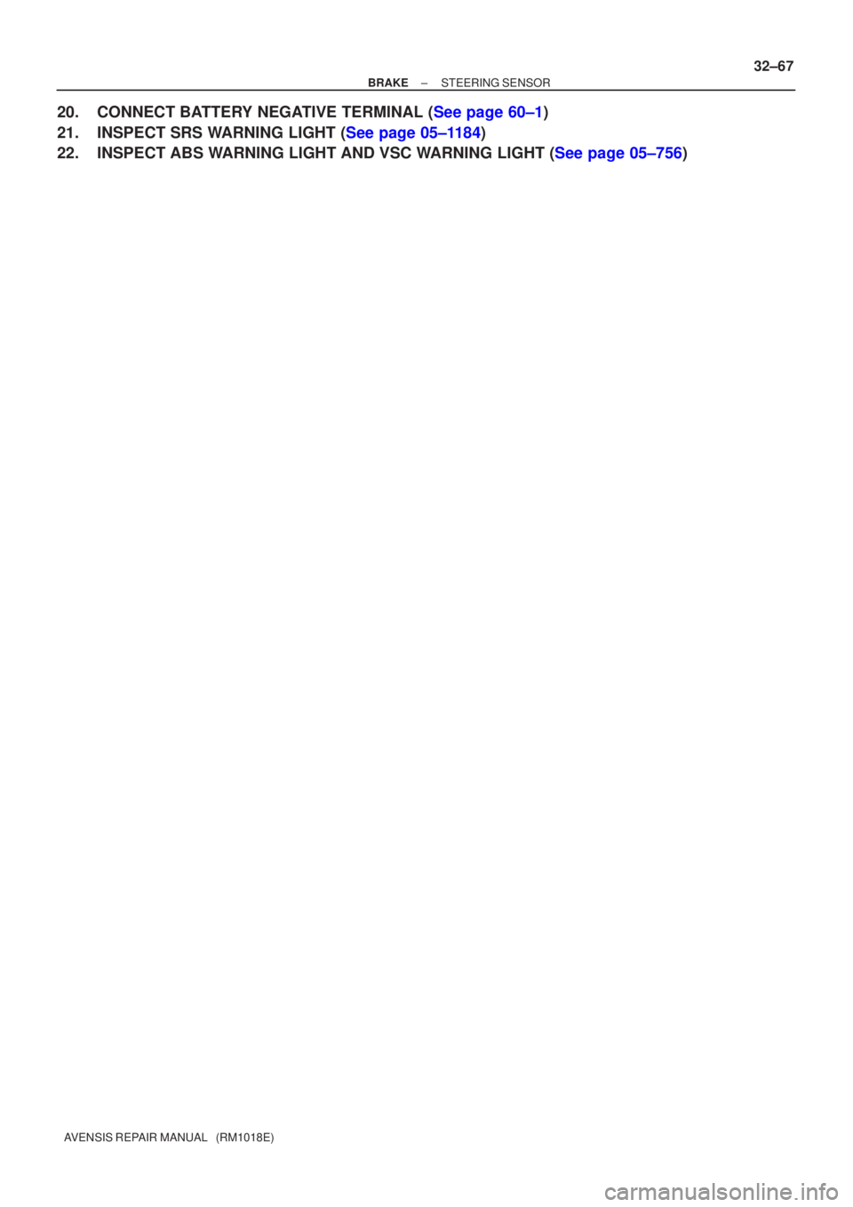
3. REMOVE SPEED SENSOR FRONT LH
(a) Disconnect the resin clip and speed sensor wire harness
from the body and clamp.
(b) Disconnect the speed sensor connector.
(c) Remove the 2 clamp bolts holding the sensor harness
from the body and shock absorber.
(d) Remove the bolt and separate the speed sensor front LH.
NOTICE:
Prevent foeingn matter from attaching to the sensor tip.
4. INSTALL SPEED SENSOR FRONT LH
(a) Install the speed sensor front LH with the bolt.
Torque: 8.0 N�m (82 kgf�cm, 71 in.�lbf)
NOTICE:
Prevent foeingn matter from attaching to the sensor tip.
Page 86 of 1690
F40024
A
B
G23166
32±60
±
BRAKE SPEED SENSOR FRONT LH
AVENSIS REPAIR MANUAL (RM1018E)
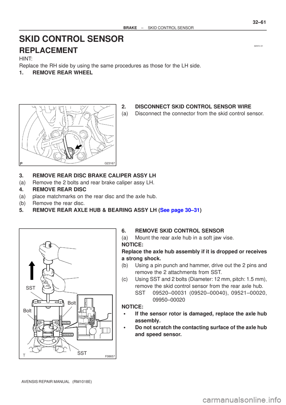
(b)Install the sensor harness clamp with the 2 bolts ºAº and ºBº to the body and shock absorber.
Torque:
Bolt A: 8.0 N �m (82 kgf �cm, 71 in. �lbf)
Bolt B: 29 N �m (296 kgf �cm, 21 ft �lbf)
NOTICE:
Do not twist the sensor wire when installing the sensor.
(c)Connect the speed sensor connector.
(d)Connect the resin clip and speed sensor wire harness to the body and clamp.
5.INSTALL FRONT FENDER LINER LH
6.INSTALL FRONT WHEEL Torque: 103 N �m (1,050 kgf �cm, 76 ft �lbf)
7.CHECK ABS SPEED SENSOR SIGNAL (See page 05±699)
Page 87 of 1690
320G5±02
F45426
F45427
F42642
±
BRAKE STEERING SENSOR
32±65
AVENSIS REPAIR MANUAL (RM1018E)
STEERING SENSOR
REPLACEMENT
1.PRECAUTION (See page 60±1)
2. REMOVE PLACE FRONT WHEELS FACING STRAIGHT AHEAD
3.DISCONNECT BATTERY NEGATIVE TERMINAL (See page 60±1)
4.REMOVE HORN BUTTON ASSY (See page 60±17)
5.REMOVE STEERING WHEEL ASSY (See page 50±9)
6.REMOVE STEERING COLUMN COVER LWR (See page 50±9)
7. REMOVE STEERING COLUMN COVER W/INSTRUMENT CLUSTER FINISH PANEL ASSY
(See page 50±9)
8.REMOVE STEERING COLUMN ASSY(See page 50±9)
9.REMOVE STEERING INTERMEDIATE SHAFT ASSY NO.2 (See page 50±9)
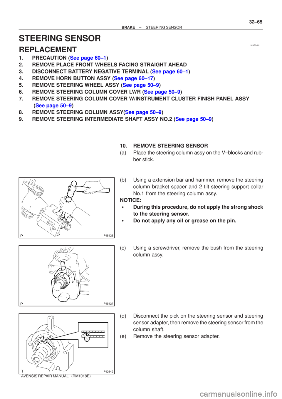
10. REMOVE STEERING SENSOR
(a) Place the steering column assy on the V±blocks and rub-ber stick.
(b) Using a extension bar and hammer, remove the steering column bracket spacer and 2 tilt steering support collar
No.1 from the steering column assy.
NOTICE:
�During this procedure, do not apply the strong shock
to the steering sensor.
�Do not apply any oil or grease on the pin.
(c) Using a screwdriver, remove the bush from the steering column assy.
(d) Disconnect the pick on the steering sensor and steering sensor adapter, then remove the steering sensor from the
column shaft.
(e) Remove the steering sensor adapter.
Page 88 of 1690
F42641
F42642
F45427
F45426
32±66
±
BRAKE STEERING SENSOR
AVENSIS REPAIR MANUAL (RM1018E)
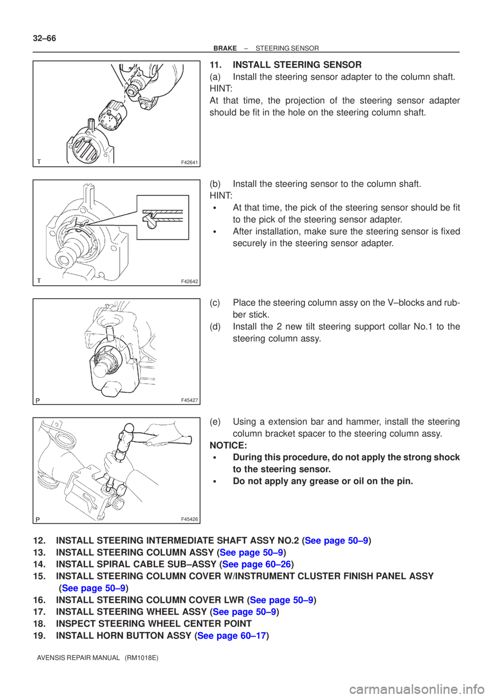
11. INSTALL STEERING SENSOR
(a) Install the steering sensor adapter to the column shaft.
HINT:
At that time, the projection of the steering sensor adapter
should be fit in the hole on the steering column shaft.
(b) Install the steering sensor to the column shaft.
HINT:
�At that time, the pick of the steering sensor should be fit
to the pick of the steering sensor adapter.
�After installation, make sure the steering sensor is fixed
securely in the steering sensor adapter.
(c) Place the steering column assy on the V±blocks and rub- ber stick.
(d) Install the 2 new tilt steering support collar No.1 to the steering column assy.
(e) Using a extension bar and hammer, install the steering column bracket spacer to the steering column assy.
NOTICE:
�During this procedure, do not apply the strong shock
to the steering sensor.
�Do not apply any grease or oil on the pin.
12.INSTALL STEERING INTERMEDIATE SHAFT ASSY NO.2 (See page 50±9)
13.INSTALL STEERING COLUMN ASSY (See page 50±9)
14.INSTALL SPIRAL CABLE SUB±ASSY (See page 60±26)
15. INSTALL STEERING COLUMN COVER W/INSTRUMENT CLUSTER FINISH PANEL ASSY (See page 50±9)
16.INSTALL STEERING COLUMN COVER LWR (See page 50±9)
17.INSTALL STEERING WHEEL ASSY (See page 50±9)
18. INSPECT STEERING WHEEL CENTER POINT
19.INSTALL HORN BUTTON ASSY (See page 60±17)
Page 89 of 1690
±
BRAKE STEERING SENSOR
32±67
AVENSIS REPAIR MANUAL (RM1018E)
20.CONNECT BATTERY NEGATIVE TERMINAL (See page 60±1)
21.INSPECT SRS WARNING LIGHT (See page 05±1184)
22.INSPECT ABS WARNING LIGHT AND VSC WARNING LIGHT (See page 05±756)
Page 97 of 1690
320GM±02
G23169
G23170
G23171
G23170
±
BRAKE YAWRATE SENSOR
32±63
AVENSIS REPAIR MANUAL (RM1018E)
YAWRATE SENSOR
REPLACEMENT
NOTICE:
�Don't use the dropped or damaged yawrate sensor.
�Free from the foreing matters between yawrate sensor braket and body.
�Make sure the sensor direction.
1.REMOVE FRONT SEAT ASSEMBLY LH (See page 72±11 or 72±16)
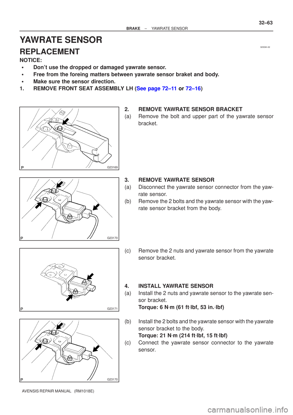
2. REMOVE YAWRATE SENSOR BRACKET
(a) Remove the bolt and upper part of the yawrate sensorbracket.
3. REMOVE YAWRATE SENSOR
(a) Disconnect the yawrate sensor connector from the yaw- rate sensor.
(b) Remove the 2 bolts and the yawrate sensor with the yaw- rate sensor bracket from the body.
(c) Remove the 2 nuts and yawrate sensor from the yawrate sensor bracket.
4. INSTALL YAWRATE SENSOR
(a) Install the 2 nuts and yawrate sensor to the yawrate sen- sor bracket.
Torque: 6 N �m (61 ft �lbf, 53 in. �lbf)
(b) Install the 2 bolts and the yawrate sensor with the yawrate sensor bracket to the body.
Torque: 21 N �m (214 ft �lbf, 15 ft �lbf)
(c) Connect the yawrate sensor connector to the yawrate sensor.