Page 69 of 1690
±
BRAKE BRAKE SYSTEM
32±3
AVENSIS REPAIR MANUAL (RM1018E)
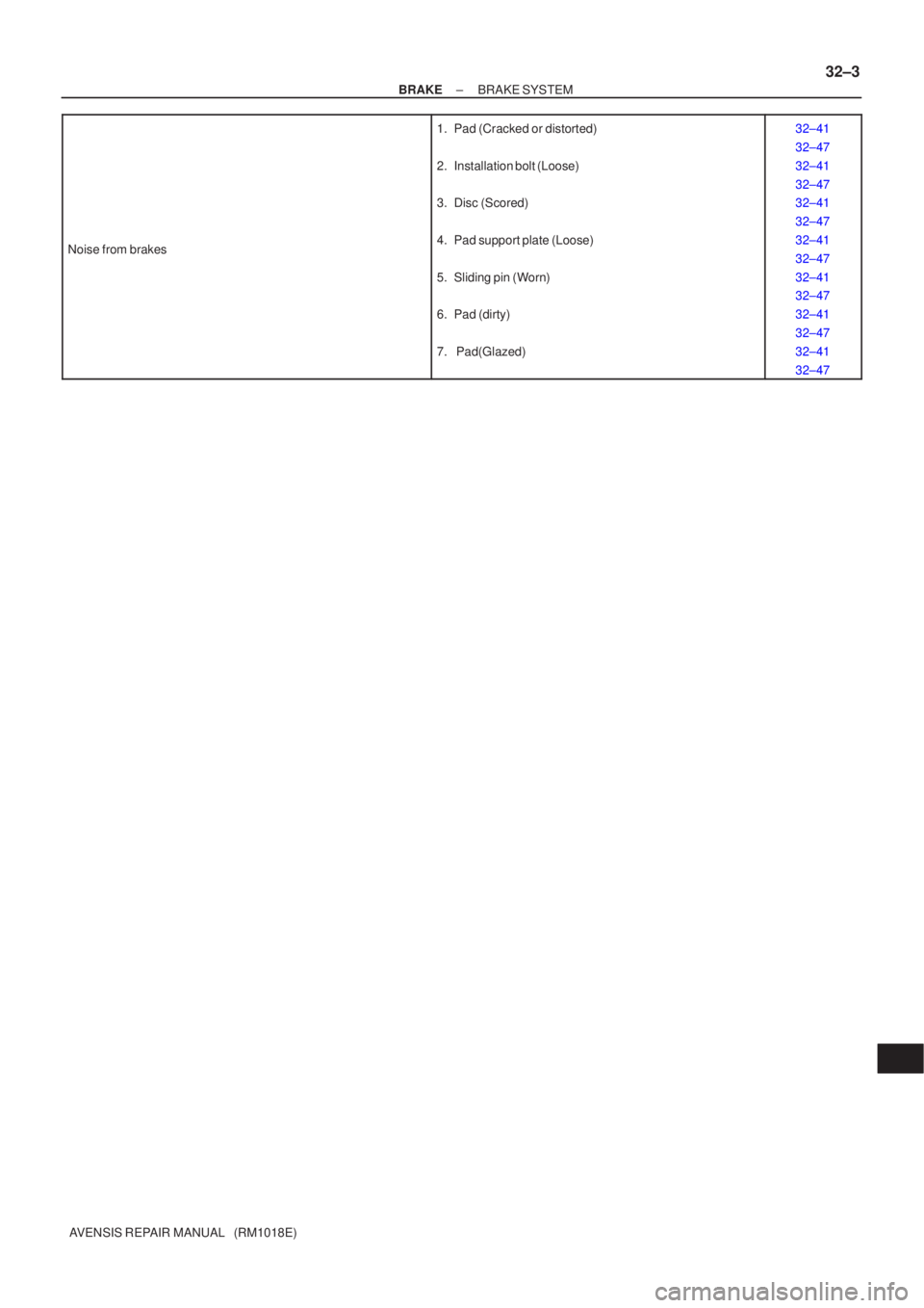
Noise from brakes
1. Pad (Cracked or distorted)
2. Installation bolt (Loose)
3. Disc (Scored)
4. Pad support plate (Loose)
5. Sliding pin (Worn)
6. Pad (dirty)
7. Pad(Glazed)32±41
32±47
32±41
32±47
32±41
32±47
32±41
32±47
32±41
32±47
32±41
32±47
32±41
32±47
Page 85 of 1690
3201P±05
G23166
F40024
G23165
G23165
± BRAKESPEED SENSOR FRONT LH
32±59
AVENSIS REPAIR MANUAL (RM1018E)
SPEED SENSOR FRONT LH
REPLACEMENT
HINT:
Replace the RH side by using the same procedures as those for the LH side.
1. REMOVE FRONT WHEEL
2. REMOVE FRONT FENDER LINER LH
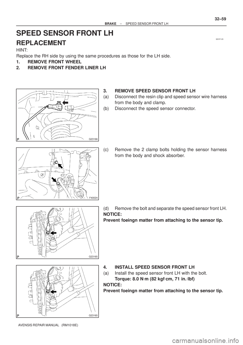
3. REMOVE SPEED SENSOR FRONT LH
(a) Disconnect the resin clip and speed sensor wire harness
from the body and clamp.
(b) Disconnect the speed sensor connector.
(c) Remove the 2 clamp bolts holding the sensor harness
from the body and shock absorber.
(d) Remove the bolt and separate the speed sensor front LH.
NOTICE:
Prevent foeingn matter from attaching to the sensor tip.
4. INSTALL SPEED SENSOR FRONT LH
(a) Install the speed sensor front LH with the bolt.
Torque: 8.0 N�m (82 kgf�cm, 71 in.�lbf)
NOTICE:
Prevent foeingn matter from attaching to the sensor tip.
Page 191 of 1690
300JY±01
������F45751
SST
C80291
F44775
C67088
30±22
±
DRIVE SHAFT / PROPELLER SHAFT FRONT AXLE HUB SUB±ASSY LH
AVENSIS REPAIR MANUAL (RM1018E)
REPLACEMENT
HINT:
Replace the RH side by the same procedures as the LH side.
1. REMOVE FRONT WHEEL
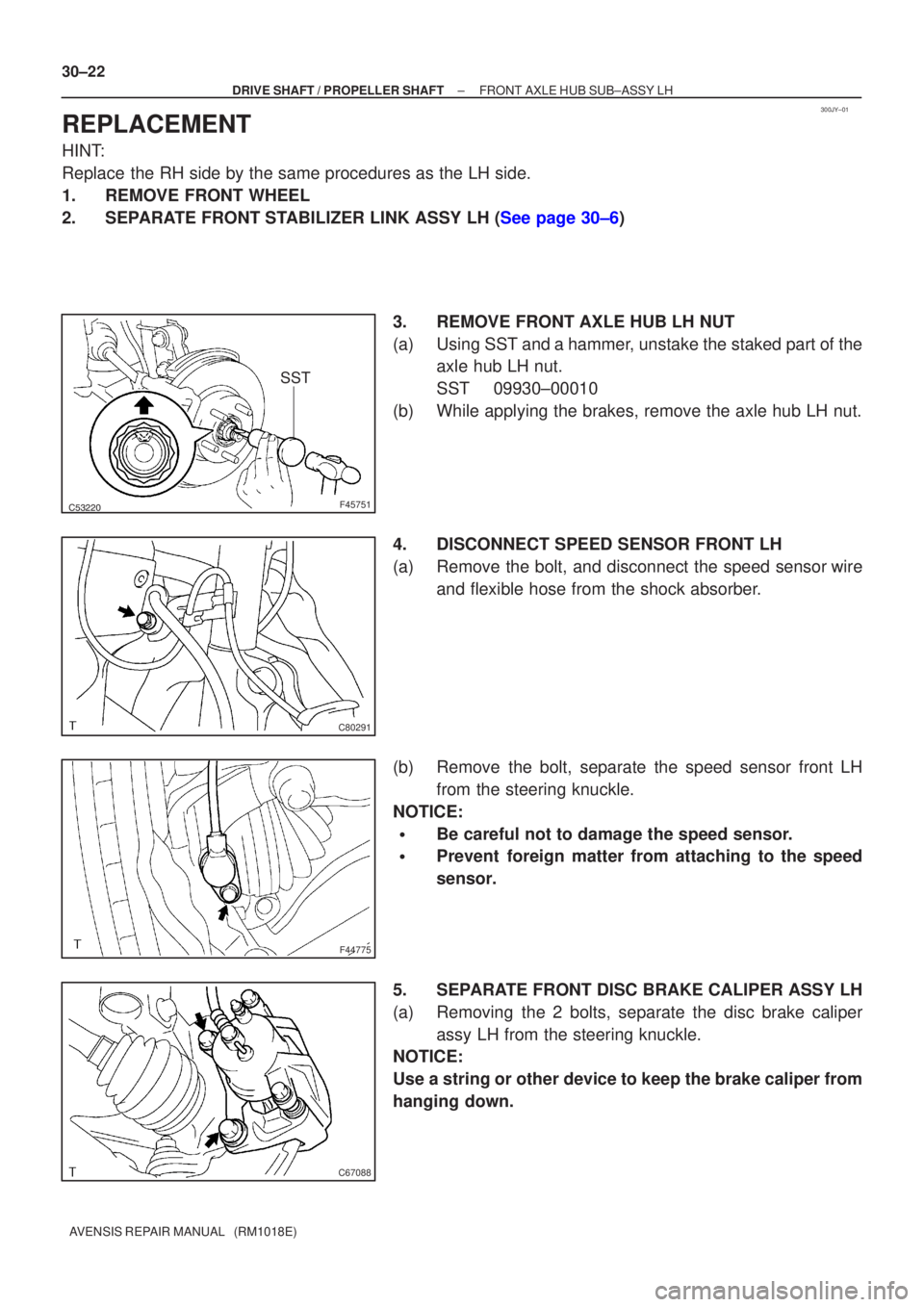
2.SEPARATE FRONT STABILIZER LINK ASSY LH (See page 30±6) 3. REMOVE FRONT AXLE HUB LH NUT
(a) Using SST and a hammer, unstake the staked part of theaxle hub LH nut.
SST 09930±00010
(b) While applying the brakes, remove the axle hub LH nut.
4. DISCONNECT SPEED SENSOR FRONT LH
(a) Remove the bolt, and disconnect the speed sensor wire and flexible hose from the shock absorber.
(b) Remove the bolt, separate the speed sensor front LH from the steering knuckle.
NOTICE:
�Be careful not to damage the speed sensor.
�Prevent foreign matter from attaching to the speed
sensor.
5. SEPARATE FRONT DISC BRAKE CALIPER ASSY LH
(a) Removing the 2 bolts, separate the disc brake caliper assy LH from the steering knuckle.
NOTICE:
Use a string or other device to keep the brake caliper from
hanging down.
Page 197 of 1690
C68609
30±28
±
DRIVE SHAFT / PROPELLER SHAFT FRONT AXLE HUB SUB±ASSY LH
AVENSIS REPAIR MANUAL (RM1018E)
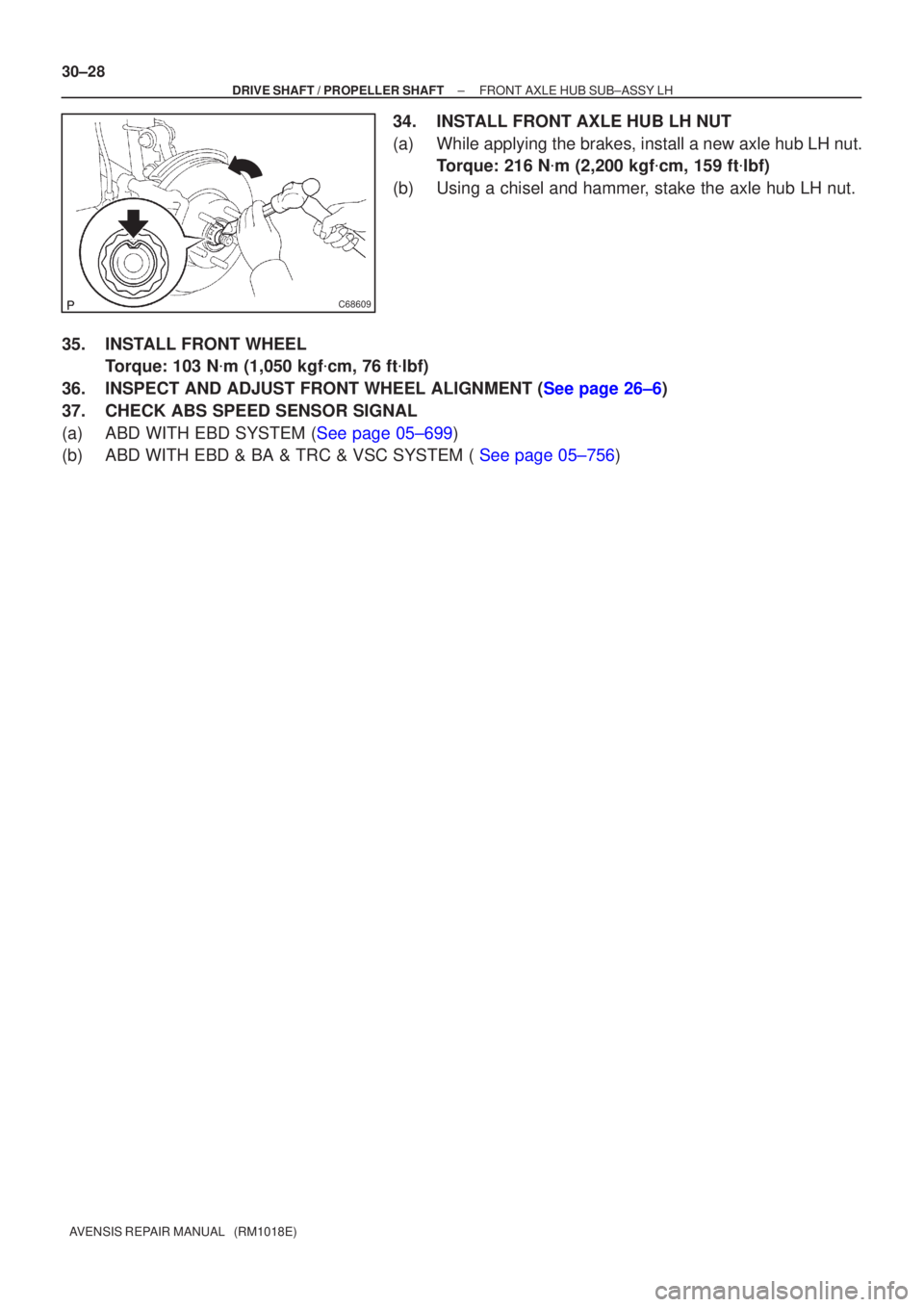
34. INSTALL FRONT AXLE HUB LH NUT
(a) While applying the brakes, install a new axle hub LH nut. Torque: 216 N �m (2,200 kgf �cm, 159 ft �lbf)
(b) Using a chisel and hammer, stake the axle hub LH nut.
35. INSTALL FRONT WHEEL Torque: 103 N �m (1,050 kgf �cm, 76 ft �lbf)
36.INSPECT AND ADJUST FRONT WHEEL ALIGNMENT (See page 26±6)
37. CHECK ABS SPEED SENSOR SIGNAL
(a)ABD WITH EBD SYSTEM (See page 05±699)
(b)ABD WITH EBD & BA & TRC & VSC SYSTEM ( See page 05±756)
Page 1312 of 1690
610E8±01
B69710
± SEAT BELTFRONT SEAT BELT
61±5
AVENSIS REPAIR MANUAL (RM1018E)
FRONT SEAT BELT
PRECAUTION
CAUTION:
Replace the faulty parts of the seat belt systems (outer belt, inner belt, bolts, nuts, adjustable shoul-
der anchor, tether anchor hardware, sill±bar, etc.)
Seat belt systems not in use at the time of a collision should also be inspected and replaced if found
to be damaged or working improperly.
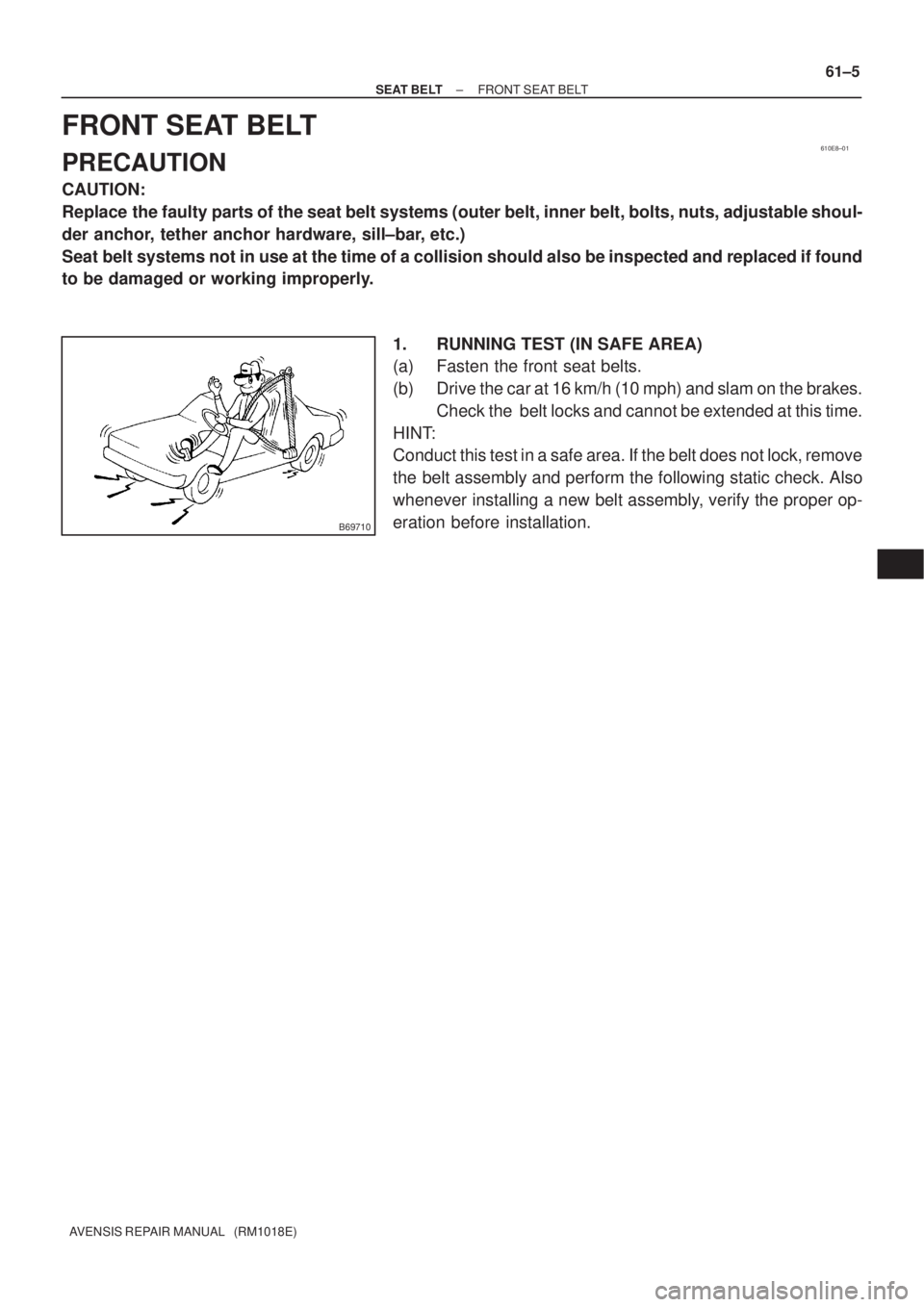
1. RUNNING TEST (IN SAFE AREA)
(a) Fasten the front seat belts.
(b) Drive the car at 16 km/h (10 mph) and slam on the brakes.
Check the belt locks and cannot be extended at this time.
HINT:
Conduct this test in a safe area. If the belt does not lock, remove
the belt assembly and perform the following static check. Also
whenever installing a new belt assembly, verify the proper op-
eration before installation.