Page 87 of 1690

STEERING SENSOR
REPLACEMENT
1.PRECAUTION (See page 60±1)
2. REMOVE PLACE FRONT WHEELS FACING STRAIGHT")
320G5±02
F45426
F45427
F42642
±
BRAKE STEERING SENSOR
32±65
AVENSIS REPAIR MANUAL (RM1018E)
STEERING SENSOR
REPLACEMENT
1.PRECAUTION (See page 60±1)
2. REMOVE PLACE FRONT WHEELS FACING STRAIGHT AHEAD
3.DISCONNECT BATTERY NEGATIVE TERMINAL (See page 60±1)
4.REMOVE HORN BUTTON ASSY (See page 60±17)
5.REMOVE STEERING WHEEL ASSY (See page 50±9)
6.REMOVE STEERING COLUMN COVER LWR (See page 50±9)
7. REMOVE STEERING COLUMN COVER W/INSTRUMENT CLUSTER FINISH PANEL ASSY
(See page 50±9)
8.REMOVE STEERING COLUMN ASSY(See page 50±9)
9.REMOVE STEERING INTERMEDIATE SHAFT ASSY NO.2 (See page 50±9)
10. REMOVE STEERING SENSOR
(a) Place the steering column assy on the V±blocks and rub-ber stick.
(b) Using a extension bar and hammer, remove the steering column bracket spacer and 2 tilt steering support collar
No.1 from the steering column assy.
NOTICE:
�During this procedure, do not apply the strong shock
to the steering sensor.
�Do not apply any oil or grease on the pin.
(c) Using a screwdriver, remove the bush from the steering column assy.
(d) Disconnect the pick on the steering sensor and steering sensor adapter, then remove the steering sensor from the
column shaft.
(e) Remove the steering sensor adapter.
Page 88 of 1690

11. INSTALL STEERING SENSOR
(a) Install the steering sensor adapter to the column shaft.
HINT:
At that tim")
F42641
F42642
F45427
F45426
32±66
±
BRAKE STEERING SENSOR
AVENSIS REPAIR MANUAL (RM1018E)
11. INSTALL STEERING SENSOR
(a) Install the steering sensor adapter to the column shaft.
HINT:
At that time, the projection of the steering sensor adapter
should be fit in the hole on the steering column shaft.
(b) Install the steering sensor to the column shaft.
HINT:
�At that time, the pick of the steering sensor should be fit
to the pick of the steering sensor adapter.
�After installation, make sure the steering sensor is fixed
securely in the steering sensor adapter.
(c) Place the steering column assy on the V±blocks and rub- ber stick.
(d) Install the 2 new tilt steering support collar No.1 to the steering column assy.
(e) Using a extension bar and hammer, install the steering column bracket spacer to the steering column assy.
NOTICE:
�During this procedure, do not apply the strong shock
to the steering sensor.
�Do not apply any grease or oil on the pin.
12.INSTALL STEERING INTERMEDIATE SHAFT ASSY NO.2 (See page 50±9)
13.INSTALL STEERING COLUMN ASSY (See page 50±9)
14.INSTALL SPIRAL CABLE SUB±ASSY (See page 60±26)
15. INSTALL STEERING COLUMN COVER W/INSTRUMENT CLUSTER FINISH PANEL ASSY (See page 50±9)
16.INSTALL STEERING COLUMN COVER LWR (See page 50±9)
17.INSTALL STEERING WHEEL ASSY (See page 50±9)
18. INSPECT STEERING WHEEL CENTER POINT
19.INSTALL HORN BUTTON ASSY (See page 60±17)
Page 130 of 1690
69067±02
B67410
± COMMUNICATION SYSTEMHIGH PITCHED HORN ASSY
69±5
AVENSIS REPAIR MANUAL (RM1018E)
HIGH PITCHED HORN ASSY
REPLACEMENT
1. REMOVE HIGH PITCHED HORN ASSY
(a) Disconnect the connector.
(b) Remove the bolt and horn.
2. INSTALL HIGH PITCHED HORN ASSY
(a) Place the stay onto the baffle part in the radiator support
upper, and then install the horn with the bolt.
Torque: 20 N�m (204 kgf�cm, 15 ft�lbf)
(b) Connect the connector.
Page 131 of 1690
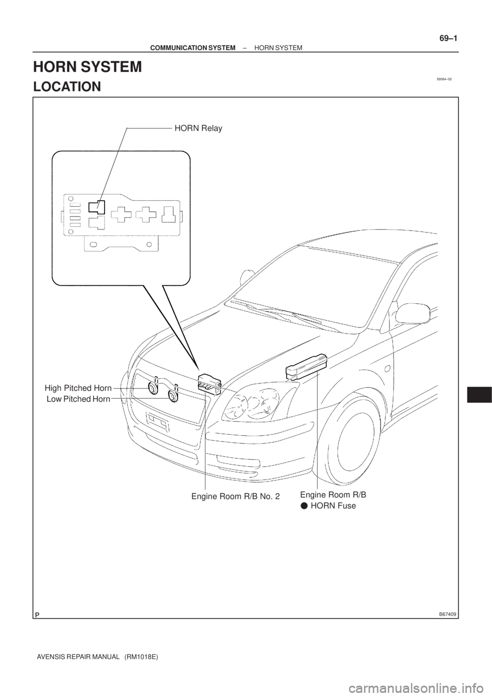
69064±02
B67409
Low Pitched HornHORN Relay
High Pitched Horn
Engine Room R/B No. 2Engine Room R/B
� HORN Fuse
± COMMUNICATION SYSTEMHORN SYSTEM
69±1
AVENSIS REPAIR MANUAL (RM1018E)
HORN SYSTEM
LOCATION
Page 132 of 1690
69065±02
69±2
±
COMMUNICATION SYSTEM HORN SYSTEM
AVENSIS REPAIR MANUAL (RM1018E)
PROBLEM SYMPTOMS TABLE
SymptomSuspected AreaSee Page
Horn does not sound
1. Horn button switch
2. High pitched horn
3. Low pitched horn
4. HORN fuse
5. HORN relay
6. Wire harness±
69±3
69±3
69±3 ±
Page 133 of 1690
69066±02
B67416
B67417
B68374
21
5
3
± COMMUNICATION SYSTEMHORN SYSTEM
69±3
AVENSIS REPAIR MANUAL (RM1018E)
INSPECTION
1. INSPECT LOW PITCHED HORN ASSY
(a) Check operation of the horn.
Standard:
Measurement ConditionSpecified Condition
Battery positive (+) �Terminal 1
Battery positive (±) �Horn bodyHorn sounds
If the result is not as specified, replace the horn assy.
2. INSPECT HIGH PITCHED HORN ASSY
(a) Check operation of the horn.
Standard:
Measurement ConditionSpecified Condition
Battery positive (+) �Terminal 1
Battery positive (±) �Horn bodyHorn sounds
If the result is not as specified, replace the horn assy.
3. INSPECT HORN RELAY ASSY
(a) Remove the HORN relay from the engine room R/B No.
2.
(b) Check the horn relay resistance.
Standard:
Tester ConnectionSpecified Condition
10 k� or higher
3 ± 5Below 1 �
(When battery voltage is applied to terminals 1 and 2)
If the result is not as specified, replace the relay assy.
Page 134 of 1690
69068±02
B67411
69±4
± COMMUNICATION SYSTEMLOW PITCHED HORN ASSY
AVENSIS REPAIR MANUAL (RM1018E)
LOW PITCHED HORN ASSY
REPLACEMENT
1. REMOVE LOW PITCHED HORN ASSY
(a) Disconnect the connector.
(b) Remove the bolt and horn.
2. INSTALL LOW PITCHED HORN ASSY
(a) Place the stay onto the baffle part in the radiator support
upper, and then install the horn with the bolt.
Torque: 20 N�m (204 kgf�cm, 15 ft�lbf)
(b) Connect the connector.
Page 170 of 1690
160MX±01
16±24
±
COOLING RADIATOR ASSY(1AZ±FE)
AVENSIS REPAIR MANUAL (RM1018E)
RADIATOR ASSY(1AZ±FE)
REPLACEMENT
1.DRAIN COOLANT (See page 16±19)
2.REMOVE RADIATOR SUPPORT OPENING COVER
3.REMOVE ENGINE ROOM COVER SIDE
4.REMOVE ENGINE UNDER COVER RH
5.DISCONNECT RADIATOR HOSE INLET
6.DISCONNECT RADIATOR HOSE OUTLET
7.REMOVE RADIATOR SUPPORT UPPER
(a)Disconnect the fan w/ motor wire harness, connector and the horn connect\
or.
(b)Remove 4 bolts, the nut and the radiator support.
8.REMOVE RADIATOR ASSY
(a)Remove 2 upper support, and radiator assembly
9.REMOVE RADIATOR SUPPORT LOWER
10.REMOVE FAN ASSY W/MOTOR
(a)Remove 6 bolts and fan w/motor.
11.INSTALL FAN ASSY W/MOTOR
12.INSTALL RADIATOR SUPPORT LOWER
13.INSTALL RADIATOR ASSY
14.INSTALL RADIATOR SUPPORT UPPER
(a)Install radiator support with 2 bolts. Torque: 19 N �m (194 kgf �cm,14 ft �lbf)
15.ADD COOLANT (See page 16±19)
16.INSPECT CHECK FOR ENGINE COOLANT LEAKS (See page 16±13)

HIGH PITCHED HORN ASSY
REPLACEMENT
1. REMOVE HIGH PITCHED HORN ASSY
(a) Disconnect the connector.")

PROBLEM SYMPTOMS TABLE
SymptomSuspected AreaSee Page
Horn does not sound
1. Horn button switch
2. High pitched hor")

INSPECTION
1. INSPECT LOW PITCHED HORN ASSY
(a) Check operation of the horn.
Standard:")

LOW PITCHED HORN ASSY
REPLACEMENT
1. REMOVE LOW PITCHED HORN ASSY
(a) Disconnect the connector.
(b")

AVENSIS REPAIR MANUAL (RM1018E)
RADIATOR ASSY(1AZ±FE)
REPLACEMENT
1.DRAIN COOLANT (See page 16±19)
2.REMOVE RADIATOR SUPPORT OPENING COVER
3.REMO")