I35431
Burner Motor
Glow Plug
Surface Sensor
Temp. Control Sensor
Flame Sensor13
Power
Heater
ECU
Connector BTerminal L
of AlternatorBattery
Metering Pump
Fuse (20 A)
Vehicle Side SW 14
9
12
5
6
3
4
1
2R
BR
B±R
G
L±Y
L
Y
L±W5
1
6
2
7
3
8
4W±B
R±G
R±B Connector A
IG
W±R (*1)
Y±R (*2)
R±L (*1)
R±Y (*2)
*1: TMC Made
*2: TMUK Made 55±16
± HEATER & AIR CONDITIONERCOMBUSTION TYPE POWER HEATER SYSTEM
AVENSIS REPAIR MANUAL (RM1018E)
2. DESCRIPTION OF DISPLAY AND BUTTONS
(a) AF: Current Value Malfunction (Blinking at current failure)
Diag: DTC (Example: 064 Flame sensor break)
Memory Clear button: Deletion of faulty memory (Press both buttons together for longer than 2 se-
conds)
> Button: Scroll up of faulty memory (The past 5 codes can be stored.)
< Button: Scroll down of faulty memory (The past 5 codes can be stored.)
3. FAULTY MEMORY
(a) The ECU is able to store up to 5 pieces of faulty memory. If it is full, the new data is written over F5.
4. WIRING DIAGRAM
SFI
SFISFI
SFISFI
SFI
D25842
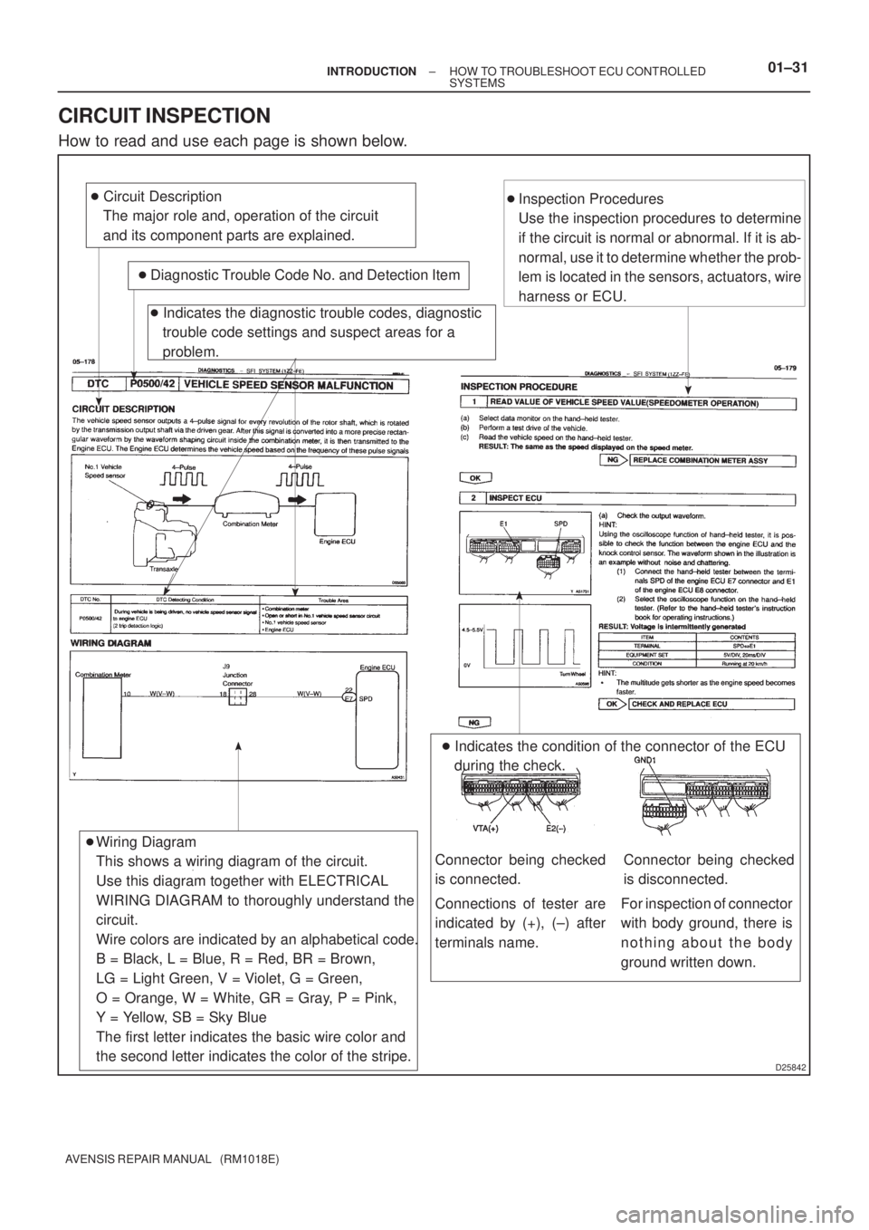
� Circuit Description
The major role and, operation of the circuit
and its component parts are explained.
� Diagnostic Trouble Code No. and Detection Item
� Indicates the diagnostic trouble codes, diagnostic
trouble code settings and suspect areas for a
problem.
Wiring Diagram
This shows a wiring diagram of the circuit.
Use this diagram together with ELECTRICAL
WIRING DIAGRAM to thoroughly understand the
circuit.
Wire colors are indicated by an alphabetical code.
B = Black, L = Blue, R = Red, BR = Brown,
LG = Light Green, V = Violet, G = Green,
O = Orange, W = White, GR = Gray, P = Pink,
Y = Yellow, SB = Sky Blue
The first letter indicates the basic wire color and
the second letter indicates the color of the stripe.�Inspection Procedures
Use the inspection procedures to determine
if the circuit is normal or abnormal. If it is ab-
normal, use it to determine whether the prob-
lem is located in the sensors, actuators, wire
harness or ECU.
� Indicates the condition of the connector of the ECU
during the check.
�
Connections of tester are
indicated by (+), (±) after
terminals name.
Connector being checked
is connected.Connector being checked
is disconnected.
For inspection of connector
with body ground, there is
nothing about the body
ground written down.
± INTRODUCTIONHOW TO TROUBLESHOOT ECU CONTROLLED
SYSTEMS01±31
AVENSIS REPAIR MANUAL (RM1018E)
CIRCUIT INSPECTION
How to read and use each page is shown below.
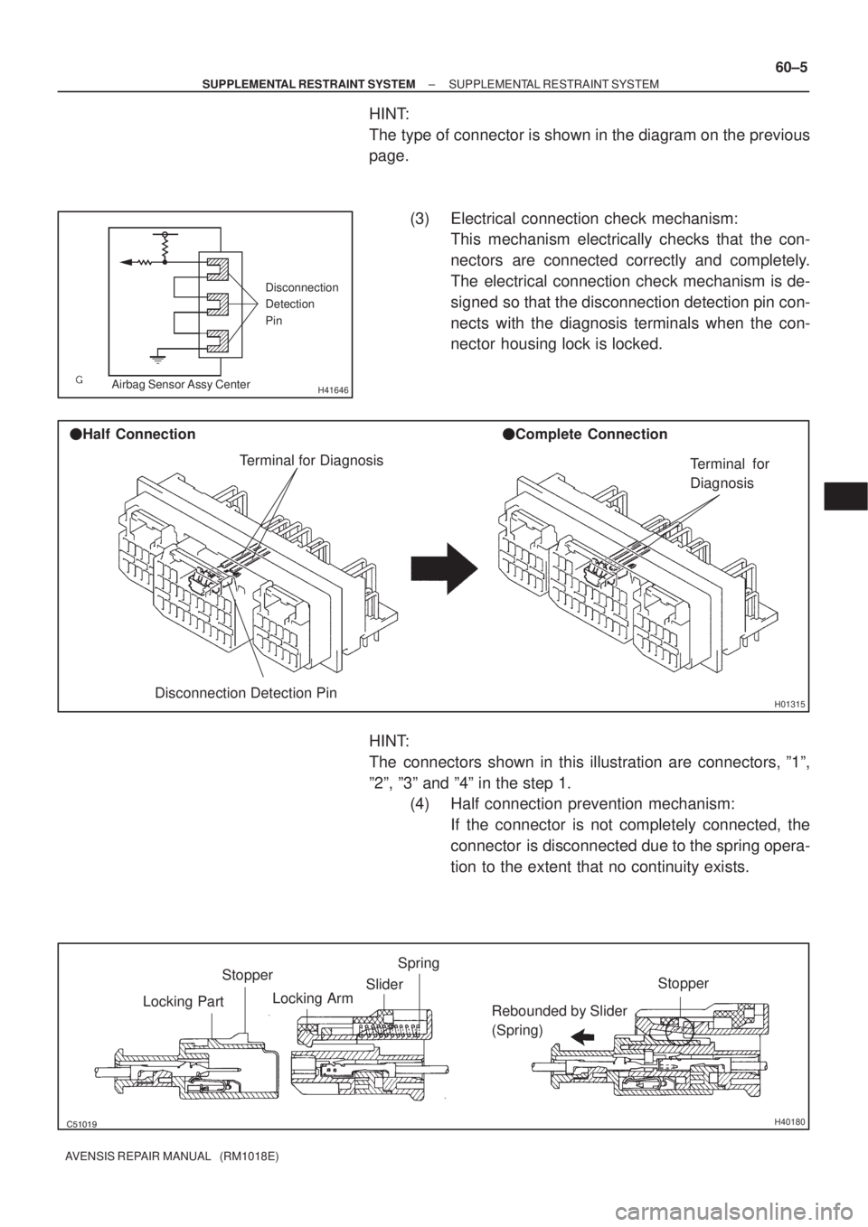
H41646
Disconnection
Detection
Pin
Airbag Sensor Assy Center
H01315
Terminal for Diagnosis
Disconnection Detection Pin �Half Connection�Complete Connection
Terminal for
Diagnosis
������H40180
Stopper
Locking PartSpring
Slider
Locking Arm
Rebounded by Slider
(Spring)Stopper
± SUPPLEMENTAL RESTRAINT SYSTEMSUPPLEMENTAL RESTRAINT SYSTEM
60±5
AVENSIS REPAIR MANUAL (RM1018E)
HINT:
The type of connector is shown in the diagram on the previous
page.
(3) Electrical connection check mechanism:
This mechanism electrically checks that the con-
nectors are connected correctly and completely.
The electrical connection check mechanism is de-
signed so that the disconnection detection pin con-
nects with the diagnosis terminals when the con-
nector housing lock is locked.
HINT:
The connectors shown in this illustration are connectors, º1º,
º2º, º3º and º4º in the step 1.
(4) Half connection prevention mechanism:
If the connector is not completely connected, the
connector is disconnected due to the spring opera-
tion to the extent that no continuity exists.

Vehicle Side SW 14
9
12
5
6
3
4
1")