710CN±02
I34628
C10±19
C10±5
± INSTRUMENT PANEL/METERCOMBINATION METER
71±3
AVENSIS REPAIR MANUAL (RM1018E)
ON±VEHICLE INSPECTION
1. INSPECT SPEEDOMETER
(a) Check the operation.
(1) Using a speedometer tester, inspect the speedometer for acceptable indication error and check
the operation of the odometer.
Reference: km/h (Europe)
Standard indicationAcceptable range
20 km/h21.0 ± 25.0 km/h
40 km/h41.7 ± 46.2 km/h
60 km/h62.7 ± 67.2 km/h
80 km/h83.4 ± 88.4 km/h
100 km/h104.3 ± 109.3 km/h
120 km/h125.1 ± 130.6 km/h
140 km/h145.8 ± 151.8 km/h
160 km/h166.2 ± 173.2 km/h
180 km/h186.9 ± 194.5 km/h
200 km/h207.7 ± 215.7 km/h
220 km/h228.4 ± 236.8 km/h
240 km/h249.2 ± 258.0 km/h
Reference: MPH (Europe)
Standard indicationAcceptable range
20 mph21.0 ± 23.5 mph
40 mph42.0 ± 44.5 mph
60 mph62.5 ± 66.0 mph
80 mph83.1 ± 87.1 mph
100 mph103.9 ± 108.4 mph
120 mph124.7 ± 129.6 mph
140 mph145.4 ± 150.7 mph
NOTICE:
Tire wear and over or under inflation will affect the indication error.
(2) Check the deflection width of the speed meter indicator.
Reference: Below 0.5 km/h (0.3 mph)
2. INSPECT OUTPUT SIGNAL OF VEHICLE SPEED
(a) Check for the signal.
(1) While driving the vehicle at the speed of 10 km/h,
check the voltage between the terminal C11±15 of
the combination meter assy and the body ground.
Standard: Fluctuation between 10 to 14 V or less is re-
peated 7 times within 1 sec.
NOTICE:
Check it with the ignition switch ON and the connector con-
nected.
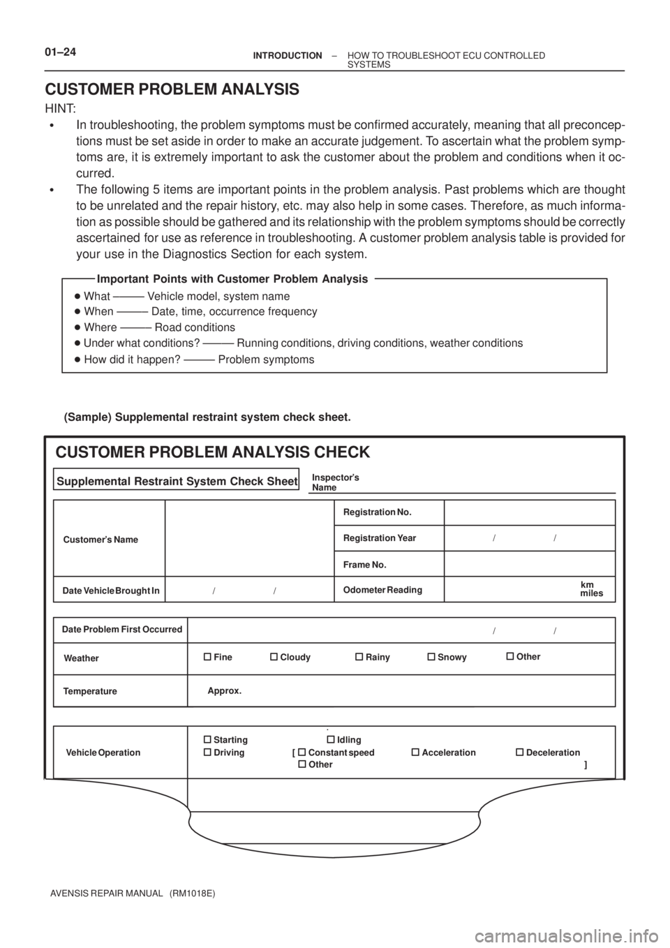
Important Points with Customer Problem Analysis
� What ±±±±± Vehicle model, system name
� When ±±±±± Date, time, occurrence frequency
� Where ±±±±± Road conditions
� Under what conditions? ±±±±± Running conditions, driving conditions, weather conditions
� How did it happen? ±±±±± Problem symptoms
(Sample) Supplemental restraint system check sheet.
Supplemental Restraint System Check Sheet
Customer's Name
Date Vehicle Brought In
Registration No.
Frame No.
Odometer Reading
km
miles
Date Problem First Occurred
Weather
Temperature
Vehicle OperationFine Cloudy
StartingIdling
Driving
Constant speed Acceleration
OtherInspector's
Name
CUSTOMER PROBLEM ANALYSIS CHECK
Registration Year
RainySnowyOther / / / /
/ /
Approx.
Deceleration [
]
01±24± INTRODUCTIONHOW TO TROUBLESHOOT ECU CONTROLLED
SYSTEMS
AVENSIS REPAIR MANUAL (RM1018E)
CUSTOMER PROBLEM ANALYSIS
HINT:
�In troubleshooting, the problem symptoms must be confirmed accurately, meaning that all preconcep-
tions must be set aside in order to make an accurate judgement. To ascertain what the problem symp-
toms are, it is extremely important to ask the customer about the problem and conditions when it oc-
curred.
�The following 5 items are important points in the problem analysis. Past problems which are thought
to be unrelated and the repair history, etc. may also help in some cases. Therefore, as much informa-
tion as possible should be gathered and its relationship with the problem symptoms should be correctly
ascertained for use as reference in troubleshooting. A customer problem analysis table is provided for
your use in the Diagnostics Section for each system.

ON±VEHICLE INSPECTION
1. INSPECT SPEEDOMETER
(a) Check the operation.
(1) Using a sp")