Page 13 of 1690
670S5±01
I35223
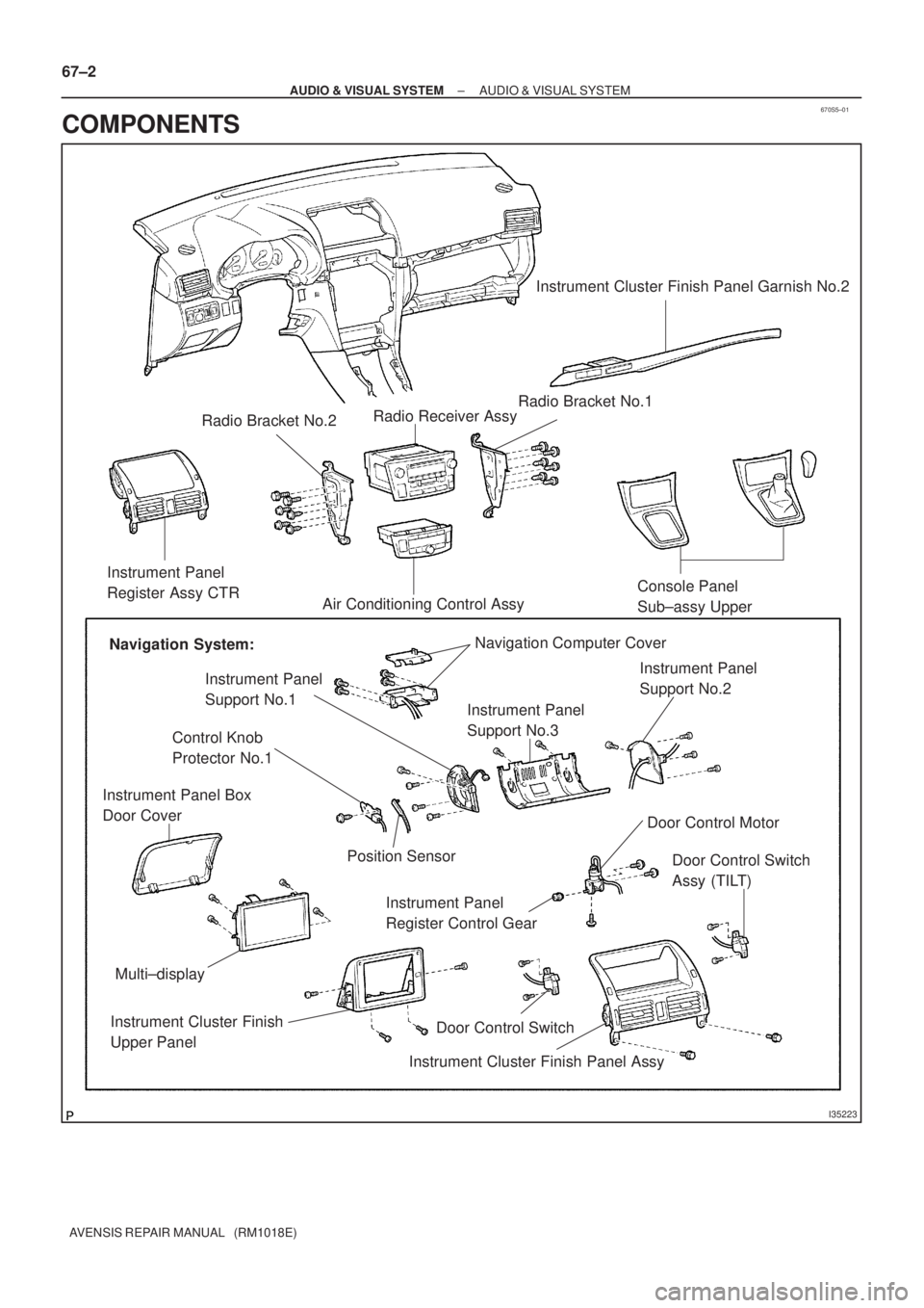
Instrument Cluster Finish Panel Garnish No.2
Radio Bracket No.2Radio Receiver Assy
Instrument Panel
Register Assy CTR
Air Conditioning Control AssyConsole Panel
Sub±assy Upper
Navigation System:Navigation Computer Cover
Instrument Panel
Support No.3 Instrument Panel
Support No.1Instrument Panel
Support No.2
Door Control Motor
Door Control Switch
Assy (TILT)
Instrument Cluster Finish Panel AssyDoor Control Switch Instrument Cluster Finish
Upper PanelMulti±display Instrument Panel Box
Door CoverRadio Bracket No.1
Instrument Panel
Register Control Gear
Control Knob
Protector No.1
Position Sensor
67±2
± AUDIO & VISUAL SYSTEMAUDIO & VISUAL SYSTEM
AVENSIS REPAIR MANUAL (RM1018E)
COMPONENTS
Page 22 of 1690
670S7±01
I351712 Claws
I35172
I35173
I35175
67±6
±
AUDIO & VISUAL SYSTEM MULTI±DISPLAY (CRT DISPLAY) DISPLAY
AVENSIS REPAIR MANUAL (RM1018E)
MULTI±DISPLAY (CRT DISPLAY) DISPLAY
REPLACEMENT
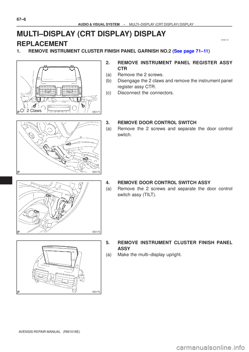
1.REMOVE INSTRUMENT CLUSTER FINISH PANEL GARNISH NO.2 (See page 71±11) 2. REMOVE INSTRUMENT PANEL REGISTER ASSYCTR
(a) Remove the 2 screws.
(b) Disengage the 2 claws and remove the instrument panel register assy CTR.
(c) Disconnect the connectors.
3. REMOVE DOOR CONTROL SWITCH
(a) Remove the 2 screws and separate the door control switch.
4. REMOVE DOOR CONTROL SWITCH ASSY
(a) Remove the 2 screws and separate the door control switch assy (TILT).
5. REMOVE INSTRUMENT CLUSTER FINISH PANEL ASSY
(a) Make the multi±display upright.
Page 23 of 1690
I35174
I35177
I35176
I351782 Clips
I35179
± AUDIO & VISUAL SYSTEMMULTI±DISPLAY (CRT DISPLAY) DISPLAY
67±7
AVENSIS REPAIR MANUAL (RM1018E)
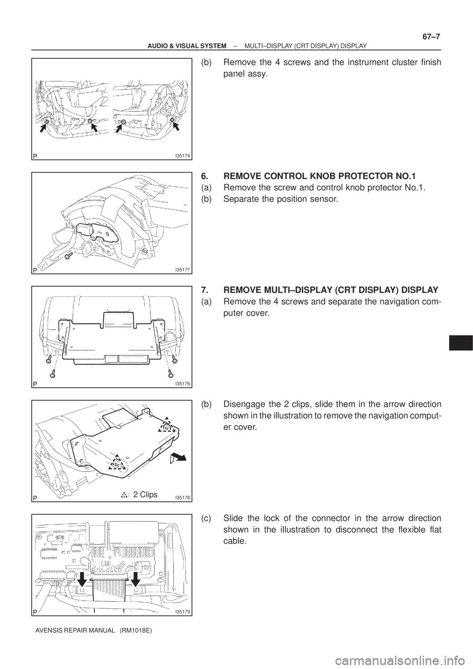
(b) Remove the 4 screws and the instrument cluster finish
panel assy.
6. REMOVE CONTROL KNOB PROTECTOR NO.1
(a) Remove the screw and control knob protector No.1.
(b) Separate the position sensor.
7. REMOVE MULTI±DISPLAY (CRT DISPLAY) DISPLAY
(a) Remove the 4 screws and separate the navigation com-
puter cover.
(b) Disengage the 2 clips, slide them in the arrow direction
shown in the illustration to remove the navigation comput-
er cover.
(c) Slide the lock of the connector in the arrow direction
shown in the illustration to disconnect the flexible flat
cable.
Page 24 of 1690
I35187
I35180
I35181
I35182
67±8
± AUDIO & VISUAL SYSTEMMULTI±DISPLAY (CRT DISPLAY) DISPLAY
AVENSIS REPAIR MANUAL (RM1018E)
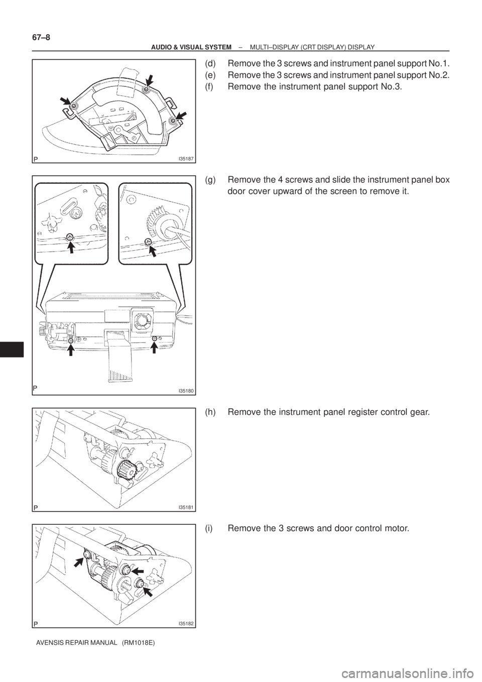
(d) Remove the 3 screws and instrument panel support No.1.
(e) Remove the 3 screws and instrument panel support No.2.
(f) Remove the instrument panel support No.3.
(g) Remove the 4 screws and slide the instrument panel box
door cover upward of the screen to remove it.
(h) Remove the instrument panel register control gear.
(i) Remove the 3 screws and door control motor.
Page 25 of 1690
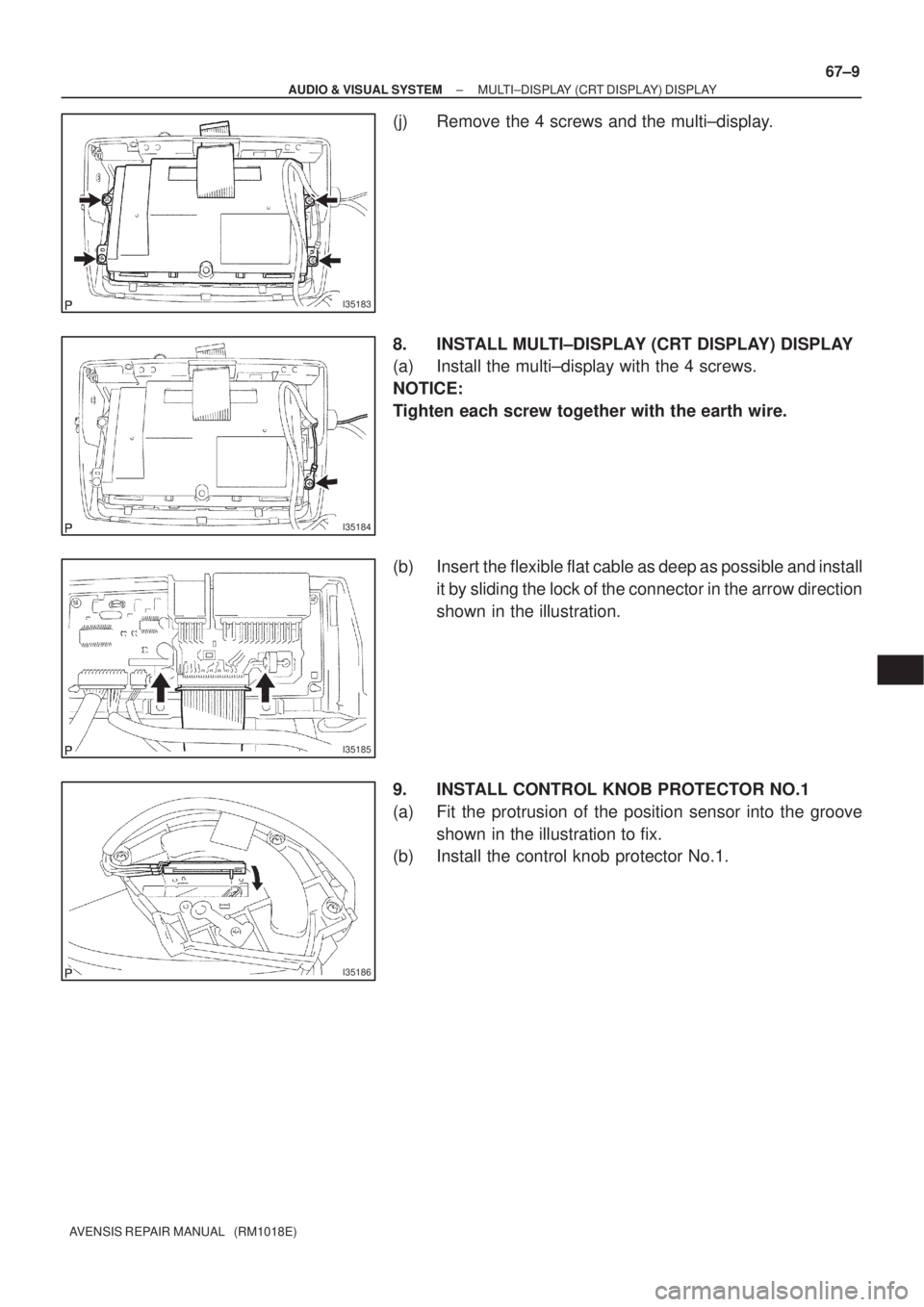
I35183
I35184
I35185
I35186
± AUDIO & VISUAL SYSTEMMULTI±DISPLAY (CRT DISPLAY) DISPLAY
67±9
AVENSIS REPAIR MANUAL (RM1018E)
(j) Remove the 4 screws and the multi±display.
8. INSTALL MULTI±DISPLAY (CRT DISPLAY) DISPLAY
(a) Install the multi±display with the 4 screws.
NOTICE:
Tighten each screw together with the earth wire.
(b) Insert the flexible flat cable as deep as possible and install
it by sliding the lock of the connector in the arrow direction
shown in the illustration.
9. INSTALL CONTROL KNOB PROTECTOR NO.1
(a) Fit the protrusion of the position sensor into the groove
shown in the illustration to fix.
(b) Install the control knob protector No.1.
Page 849 of 1690
550ZG±01
������������������I12508
Connector B
DTC Check Harness
Current DisplayControl PanelPast Record DTC Display
Memory Clear Button
DTC Calling Button
DTC Calling ButtonºHeatingº
Symbol In Normal
In Malfunction Connector A
± HEATER & AIR CONDITIONERCOMBUSTION TYPE POWER HEATER SYSTEM
55±15
AVENSIS REPAIR MANUAL (RM1018E)
COMBUSTION TYPE POWER HEATER SYSTEM
ON±VEHICLE INSPECTION
NOTICE:
�If the glow plug breaks, the ECU detects the breakage and stops the automatic operation, so
the burner heater does not activate. (For other failures, similarly activated.)
�The cause of failures (such as voltage malfunction, overheating malfunction, short±circuit or
breakage of functional components, etc.) and repair methods are shown by connecting the DTC
tester and reading the DTC.
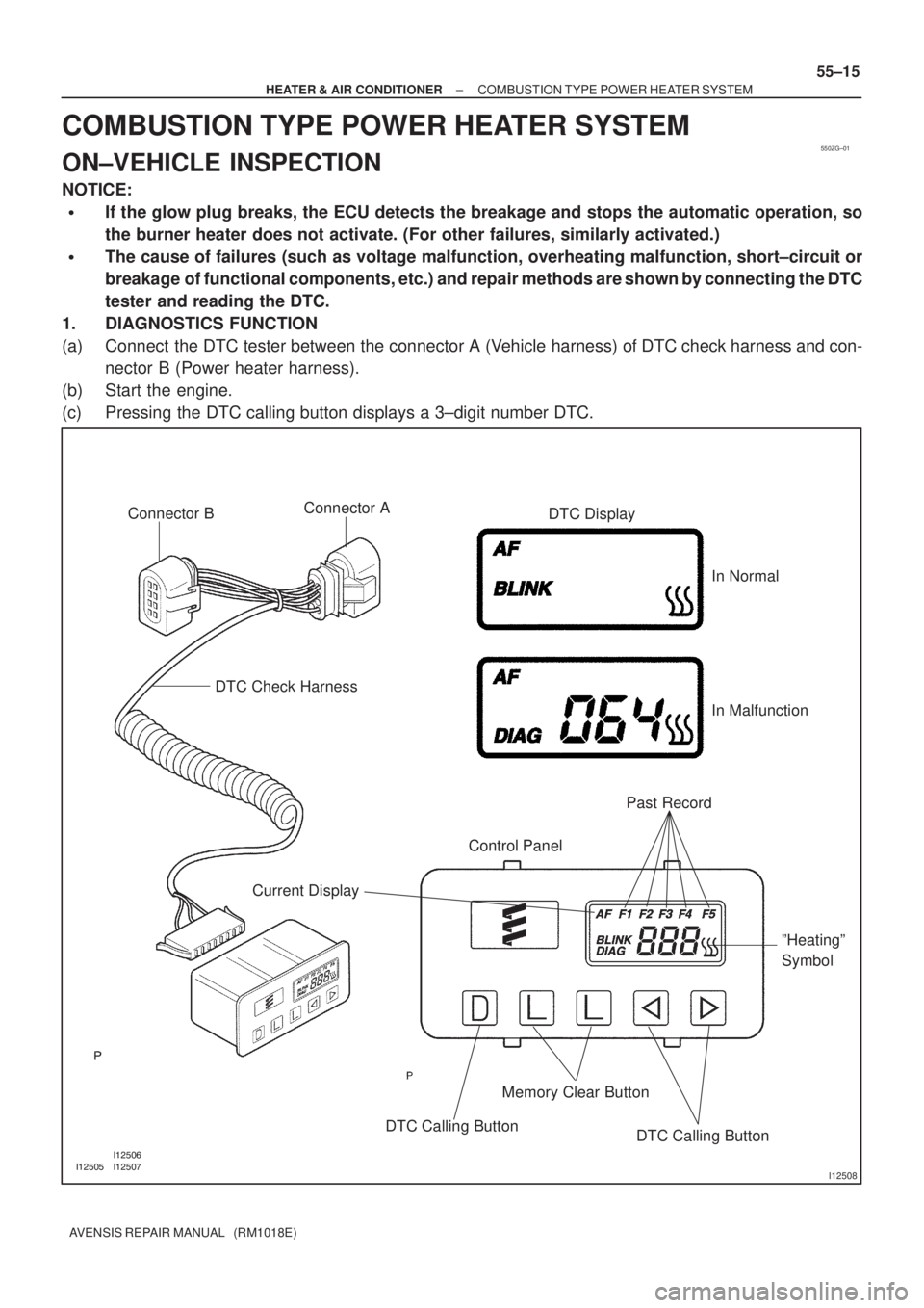
1. DIAGNOSTICS FUNCTION
(a) Connect the DTC tester between the connector A (Vehicle harness) of DTC check harness and con-
nector B (Power heater harness).
(b) Start the engine.
(c) Pressing the DTC calling button displays a 3±digit number DTC.
Page 850 of 1690
I35431
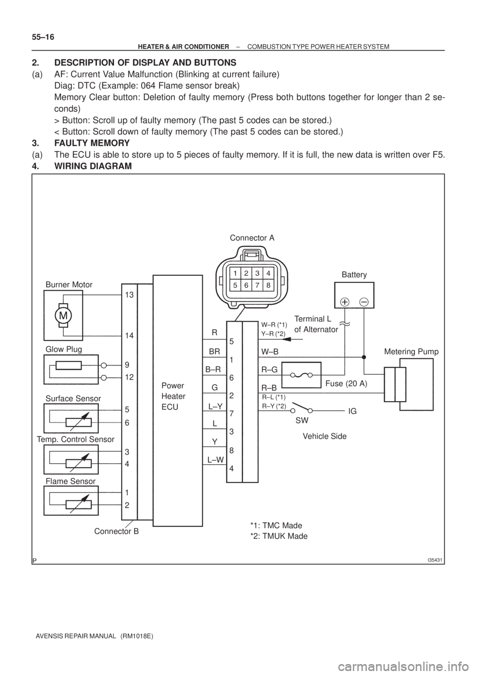
Burner Motor
Glow Plug
Surface Sensor
Temp. Control Sensor
Flame Sensor13
Power
Heater
ECU
Connector BTerminal L
of AlternatorBattery
Metering Pump
Fuse (20 A)
Vehicle Side SW 14
9
12
5
6
3
4
1
2R
BR
B±R
G
L±Y
L
Y
L±W5
1
6
2
7
3
8
4W±B
R±G
R±B Connector A
IG
W±R (*1)
Y±R (*2)
R±L (*1)
R±Y (*2)
*1: TMC Made
*2: TMUK Made 55±16
± HEATER & AIR CONDITIONERCOMBUSTION TYPE POWER HEATER SYSTEM
AVENSIS REPAIR MANUAL (RM1018E)
2. DESCRIPTION OF DISPLAY AND BUTTONS
(a) AF: Current Value Malfunction (Blinking at current failure)
Diag: DTC (Example: 064 Flame sensor break)
Memory Clear button: Deletion of faulty memory (Press both buttons together for longer than 2 se-
conds)
> Button: Scroll up of faulty memory (The past 5 codes can be stored.)
< Button: Scroll down of faulty memory (The past 5 codes can be stored.)
3. FAULTY MEMORY
(a) The ECU is able to store up to 5 pieces of faulty memory. If it is full, the new data is written over F5.
4. WIRING DIAGRAM
Page 851 of 1690
± HEATER & AIR CONDITIONERCOMBUSTION TYPE POWER HEATER SYSTEM
55±17
AVENSIS REPAIR MANUAL (RM1018E)
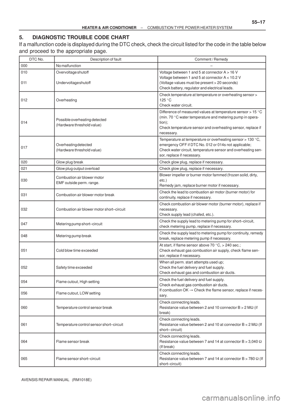
5. DIAGNOSTIC TROUBLE CODE CHART
If a malfunction code is displayed during the DTC check, check the circuit listed for the code in the table below
and proceed to the appropriate page.
DTC No.Description of faultComment / Remedy
000No malfunction±
010
011Overvoltage shutoff
Undervoltage shutoffVoltage between 1 and 5 at connector A > 16 V
Voltage between 1 and 5 at connector A < 10.2 V
(Voltage values must be present > 20 seconds)
Check battery, regulator and electrical leads.
012Overheating
Check temperature at temperature or overheating sensor >
125 �C
Check water circuit.
014Possible overheating detected
(Hardware threshold value)
Difference of measured values at temperature sensor > 15 �C
(min. 70 �C water temperature and metering pump in opera-
tion);
Check temperature sensor and overheating sensor, replace if
necessary.
017Overheating detected
(Hardware threshold value)
Temperature at temperature or overheating sensor > 130 �C,
emergency OFF if DTC No. 012 or 014s not applicable;
Check water circuit, temperature sensor and overheating sen-
sor, replace if necessary.
020Glow plug breakCheck glow plug, replace if necessary.
021Glow plug output overloadCheck glow plug, replace if necessary.
030Combustion air blower motor
EMF outside perm. range.Blower impeller or burner motor fammed (frozen solid, dirty,
etc.)
Remedy jam, replace burner motor if necessary.
031Combustion air blower motor breakCheck the lead to combustion air motor (burner motor) for
continuity, replace if necessary.
032Combustion air blower motor short±circuit
Check combustion air blower motor (burner motor), replace if
necessary.
Check supply lead (chafed, etc.).
047Metering pump short±circuitCheck the supply lead to metering pump for short±circuit,
check metering pump, replace if necessary.
048Metering pump breakCheck the supply lead to metering pump for continuity, remedy
break, replace metering pump if necessary.
051Cold blow time exceeded
At start, if flame sensor above 70 �C, > 240 sec.;
Check exhaust gas combustion air supply, check flame sen-
sor, replace if necessary.
052Safety time exceeded
When all perm. start attempts used up;
Check the fuel delivery and fuel supply.
Check exhaust gas and combustion air ducts.
054Flame cutout, High settingCheck the fuel delivery and fuel supply.
Check exhaust gas combustion air ducts.
056Flame cutout, LOW setting
Check exhaust gas combustion air ducts.
If combustion OK � Check the flame sensor, replace if neces-
sary.
060Temperature control sensor break
Check connecting leads.
Resistance value between 2 and 10 connector B > 2 M� (if
break)
061Temperature control sensor short±circuit
Check connecting leads.
Resistance value between 2 and 10 at connector B < 2 M� (If
short± circuit)
064Flame sensor break
Check connecting leads.
Resistance value between 7 and 14 at connector B > 3,040 �
(If break)
065Flame sensor short±circuit
Check connecting leads.
Resistance value between 7 and 14 at connector B > 780 � (If
short±circuit)