Page 195 of 1690
C83023
C80293
30±26
±
DRIVE SHAFT / PROPELLER SHAFT FRONT AXLE HUB SUB±ASSY LH
AVENSIS REPAIR MANUAL (RM1018E)
19.INSTALL LOWER BALL JOINT ASSY FRONT LH
(a)Install the lower ball joint and torque the nut. Torque: 103 N �m (1,050 kgf �cm, 76 ft �lbf)
(b)Install a new cotter pin.
NOTICE:
If the holes for the cotter pin are not aligned, tighten the nut up to 6\
0 � further.
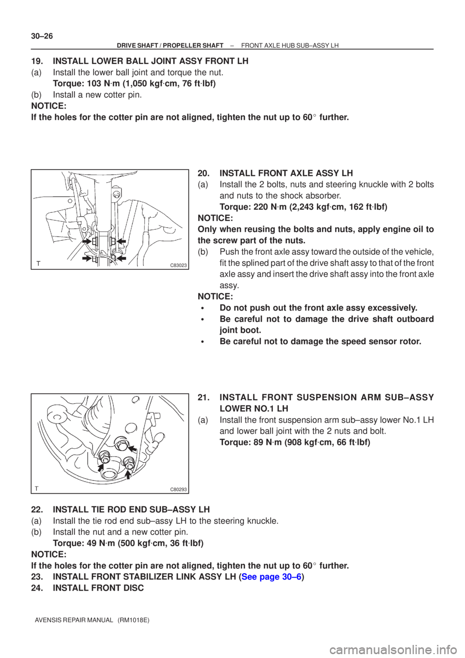
20.INSTALL FRONT AXLE ASSY LH
(a)Install the 2 bolts, nuts and steering knuckle with 2 bolts and nuts to the shock absorber.
Torque: 220 N �m (2,243 kgf �cm, 162 ft �lbf)
NOTICE:
Only when reusing the bolts and nuts, apply engine oil to
the screw part of the nuts.
(b)Push the front axle assy toward the outside of the vehicle, fit the splined part of the drive shaft assy to that of the front
axle assy and insert the drive shaft assy into the front axle
assy.
NOTICE:
�Do not push out the front axle assy excessively.
�Be careful not to damage the drive shaft outboard
joint boot.
�Be careful not to damage the speed sensor rotor.
21.INSTALL FRONT SUSPENSION ARM SUB±ASSY LOWER NO.1 LH
(a)Install the front suspension arm sub±assy lower No.1 LH and lower ball joint with the 2 nuts and bolt.
Torque: 89 N �m (908 kgf �cm, 66 ft �lbf)
22.INSTALL TIE ROD END SUB±ASSY LH
(a)Install the tie rod end sub±assy LH to the steering knuckle.
(b)Install the nut and a new cotter pin. Torque: 49 N �m (500 kgf �cm, 36 ft �lbf)
NOTICE:
If the holes for the cotter pin are not aligned, tighten the nut up to 6\
0 � further.
23.INSTALL FRONT STABILIZER LINK ASSY LH (See page 30±6)
24. INSTALL FRONT DISC
Page 434 of 1690
A77302
14±162
±
ENGINE MECHANICAL CYLINDER HEAD GASKET(1AZ±FE)
AVENSIS REPAIR MANUAL (RM1018E)
22.REMOVE ENGINE SERVICE COVER BRACKET RH (RHD(W/ AIR CONDITIONER) STEERING POSITION TYPE)
(a)Remove the bolt and the engine service cover bracket RH.
23.REMOVE CYLINDER HEAD COVER SUB±ASSY (See page 14±139)
24.SET NO. 1 CYLINDER TO TDC/COMPRESSION (See page 14±139)
25.REMOVE ENGINE MOUNTING BRACKET NO.2 RH (See page 14±139)
26.REMOVE TRANSVERSE ENGINE ENGINE MOUNTING INSULATOR (See page 14±139)
27.REMOVE CRANKSHAFT PULLEY (See page 14±139)
SST09213±54015 (91651±60855), 09330±00021, 09950±50013 (0995\
1±05010, 09952±05010, 09953±05020, 09954±05021)
28.REMOVE CHAIN TENSIONER ASSY NO.1 (See page 14±139)
29.REMOVE CRANKSHAFT POSITION SENSOR (See page 18±17)
30.REMOVE OIL PAN SUB±ASSY (See page 14±139) SST09032±00100
31.REMOVE V±RIBBED BELT TENSIONER ASSY (See page 14±139)
32.REMOVE TIMING CHAIN OR BELT COVER SUB±ASSY (See page 14±139)
33.REMOVE CRANKSHAFT POSITION SENSOR PLATE NO.1
34.REMOVE CHAIN TENSIONER SLIPPER
35.REMOVE CHAIN VIBRATION DAMPER NO.1
36.REMOVE TIMING CHAIN GUIDE (See page 14±139)
37.REMOVE CHAIN SUB±ASSY
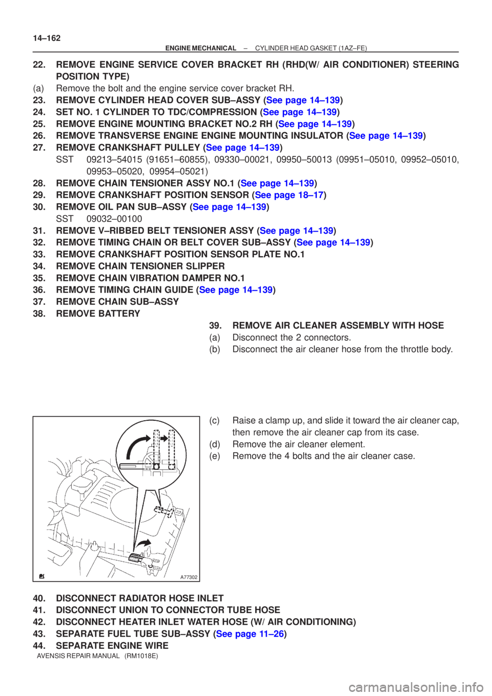
38.REMOVE BATTERY 39.REMOVE AIR CLEANER ASSEMBLY WITH HOSE
(a)Disconnect the 2 connectors.
(b)Disconnect the air cleaner hose from the throttle body.
(c)Raise a clamp up, and slide it toward the air cleaner cap,then remove the air cleaner cap from its case.
(d)Remove the air cleaner element.
(e)Remove the 4 bolts and the air cleaner case.
40.DISCONNECT RADIATOR HOSE INLET
41.DISCONNECT UNION TO CONNECTOR TUBE HOSE
42.DISCONNECT HEATER INLET WATER HOSE (W/ AIR CONDITIONING)
43.SEPARATE FUEL TUBE SUB±ASSY (See page 11±26)
44. SEPARATE ENGINE WIRE
Page 443 of 1690
A77302
A77353
±
ENGINE MECHANICAL CYLINDER HEAD GASKET(1AZ±FSE)
14±257
AVENSIS REPAIR MANUAL (RM1018E)
(e)Raise a clamp up, and slide it toward the air cleaner cap,
then remove the air cleaner cap from its case.
(f)Remove the air cleaner element.
(g)Remove the 4 bolts and the air cleaner case.
43.DISCONNECT RADIATOR HOSE INLET
44.DISCONNECT UNION TO CONNECTOR TUBE HOSE
45.DISCONNECT HEATER INLET WATER HOSE
46.SEPARATE FUEL TUBE SUB±ASSY
47.SEPARATE ENGINE WIRE
48.REMOVE THROTTLE BODY ASSY (See page 10±44)
49. REMOVE CHARCOAL CANISTER ASSY 50. REMOVE INTAKE MANIFOLD
(a) Remove the 5 bolts and 2 nuts.
(b) Disconnect the 2 vacuum hoses.
(c) Remove the 2 stud bolts.
(d) Remove the intake manifold and insulator.
51. REMOVE INTAKE AIR CONTROL VALVE ASSY
(a) Remove the intake air control valve and gasket.
52. REMOVE MANIFOLD CONVERTER INSULATOR NO.1
(a) Disconnect the oxygen sensor connector.
(b) Remove the 2 bolts and nut, and then remove the manifold insulator.
Page 522 of 1690
A77302
A77300
A77299
14±122
± ENGINE MECHANICALPARTIAL ENGINE ASSY (1AZ±FE)
AVENSIS REPAIR MANUAL (RM1018E)
20. REMOVE BATTERY
21. REMOVE AIR CLEANER ASSEMBLY WITH HOSE
(a) Disconnect 2 connectors.
(b) Disconnect the air cleaner hose from the throttle body.
(c) Raise a clamp up, and slide it toward the air cleaner cap,
then remove the air cleaner cap from its case.
(d) Remove the air cleaner element.
(e) Remove 4 bolts and the air cleaner case.
22. REMOVE BATTERY CARRIER
(a) Remove 4 bolts and the battery carrier.
23. REMOVE RADIATOR RESERVE TANK SUB±ASSY
(a) Remove 2 bolts and the radiator reserve tank.
24. SEPARATE RETURN TUBE SUB±ASSY
(a) Remove 3 bolts as shown in the illustration.
25. SEPARATE VANE PUMP OIL RESERVOIR ASSY
Page 764 of 1690
WRONG CORRECT
Delivery Pipe New O±ring
Injector
A51878
Delivery Pipe
O±ring
Grommet
B09613
O±ring
Retainer Pipe
Nylon Tube
Housing
A50709
A75343
Fuel Pipe Clamp No.2
A60818
SST 11±16
± FUELFUEL SYSTEM (1AZ±FE)
AVENSIS REPAIR MANUAL (RM1018E)
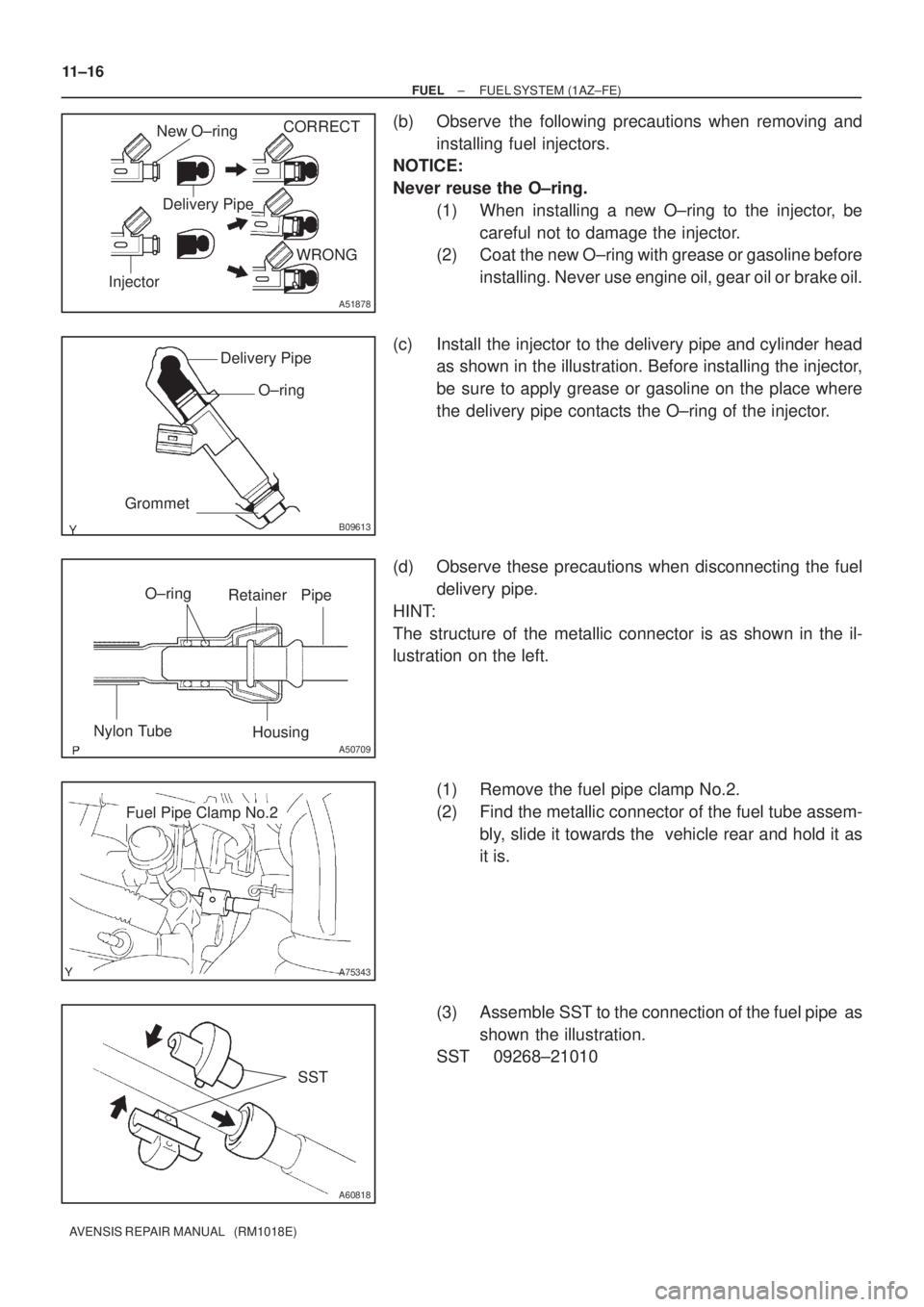
(b) Observe the following precautions when removing and
installing fuel injectors.
NOTICE:
Never reuse the O±ring.
(1) When installing a new O±ring to the injector, be
careful not to damage the injector.
(2) Coat the new O±ring with grease or gasoline before
installing. Never use engine oil, gear oil or brake oil.
(c) Install the injector to the delivery pipe and cylinder head
as shown in the illustration. Before installing the injector,
be sure to apply grease or gasoline on the place where
the delivery pipe contacts the O±ring of the injector.
(d) Observe these precautions when disconnecting the fuel
delivery pipe.
HINT:
The structure of the metallic connector is as shown in the il-
lustration on the left.
(1) Remove the fuel pipe clamp No.2.
(2) Find the metallic connector of the fuel tube assem-
bly, slide it towards the vehicle rear and hold it as
it is.
(3) Assemble SST to the connection of the fuel pipe as
shown the illustration.
SST 09268±21010
Page 765 of 1690
SST
Retainer
(at 4 places)
Insert
A50705
A60083
Fuel Pipe
Clamp No.1
A
A
B12941
B12944
A82344
Vinyl Bag or plastic Bag
± FUELFUEL SYSTEM (1AZ±FE)
11±17
AVENSIS REPAIR MANUAL (RM1018E)
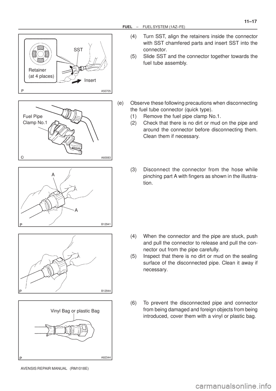
(4) Turn SST, align the retainers inside the connector
with SST chamfered parts and insert SST into the
connector.
(5) Slide SST and the connector together towards the
fuel tube assembly.
(e) Observe these following precautions when disconnecting
the fuel tube connector (quick type).
(1) Remove the fuel pipe clamp No.1.
(2) Check that there is no dirt or mud on the pipe and
around the connector before disconnecting them.
Clean them if necessary.
(3) Disconnect the connector from the hose while
pinching part A with fingers as shown in the illustra-
tion.
(4) When the connector and the pipe are stuck, push
and pull the connector to release and pull the con-
nector out from the pipe carefully.
(5) Inspect that there is no dirt or mud on the sealing
surface of the disconnected pipe. Clean it away if
necessary.
(6) To prevent the disconnected pipe and connector
from being damaged and foreign objects from being
introduced, cover them with a vinyl or plastic bag.
Page 775 of 1690
O±ring
Delivery Pipe InjectorCORRECT
WRONG
B10707
A75345
Delivery Pipe
InsulatorGrommetO±ring
Insulator
Delivery Pipe
O±ring
1ZZ±FE
3ZZ±FE
O±ring
Retainer Pipe
Nylon Tube
Housing
A50709
A75344
Fuel Pipe Clamp No.2
11±2
± FUELFUEL SYSTEM (1ZZ±FE/3ZZ±FE)
AVENSIS REPAIR MANUAL (RM1018E)
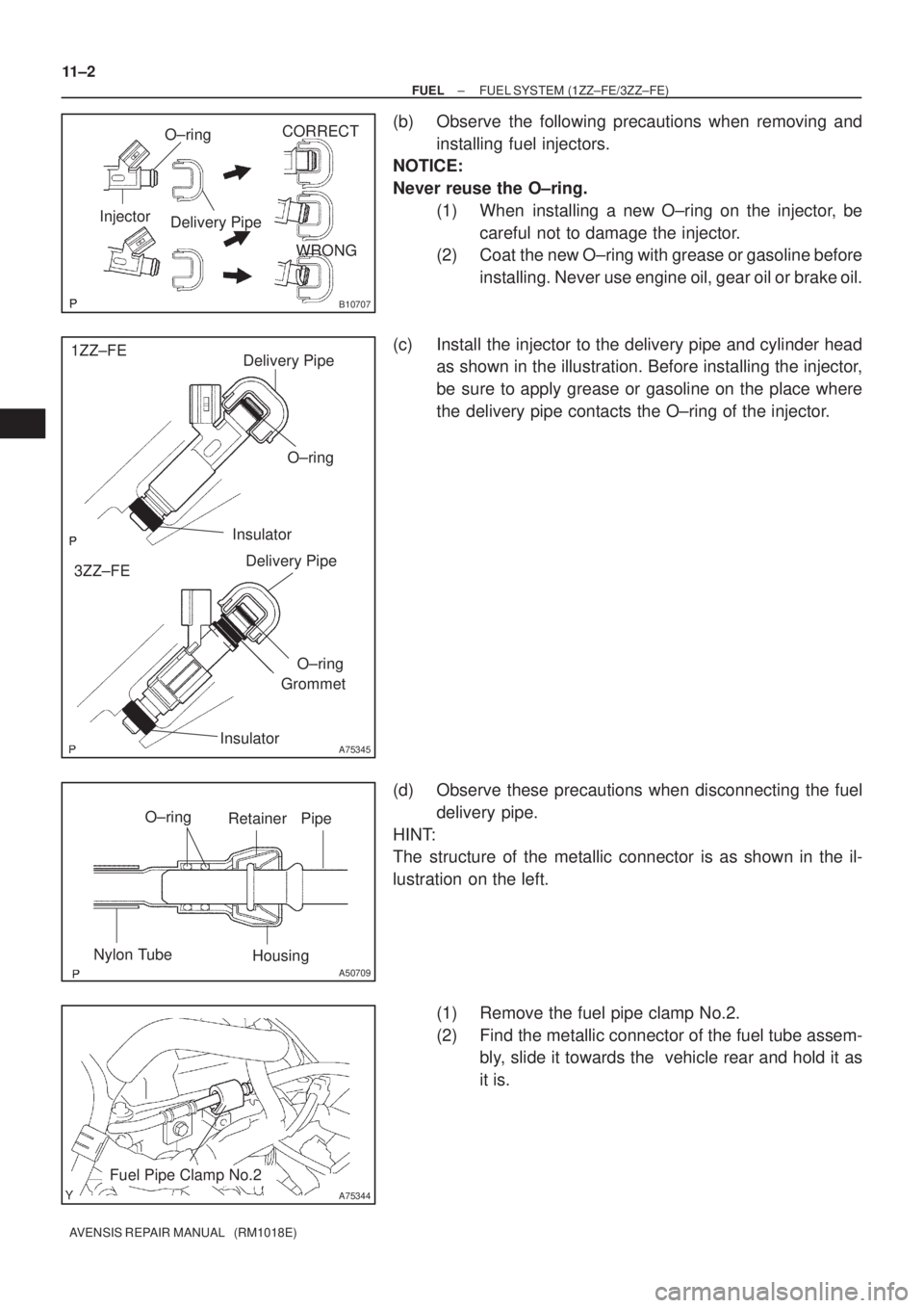
(b) Observe the following precautions when removing and
installing fuel injectors.
NOTICE:
Never reuse the O±ring.
(1) When installing a new O±ring on the injector, be
careful not to damage the injector.
(2) Coat the new O±ring with grease or gasoline before
installing. Never use engine oil, gear oil or brake oil.
(c) Install the injector to the delivery pipe and cylinder head
as shown in the illustration. Before installing the injector,
be sure to apply grease or gasoline on the place where
the delivery pipe contacts the O±ring of the injector.
(d) Observe these precautions when disconnecting the fuel
delivery pipe.
HINT:
The structure of the metallic connector is as shown in the il-
lustration on the left.
(1) Remove the fuel pipe clamp No.2.
(2) Find the metallic connector of the fuel tube assem-
bly, slide it towards the vehicle rear and hold it as
it is.
Page 776 of 1690
A60818
SST
SST
Retainer
(at 4 places)
Insert
A50705
A60083
Fuel Pipe
Clamp No.1
A
A
B12941
B12944
± FUELFUEL SYSTEM (1ZZ±FE/3ZZ±FE)
11±3
AVENSIS REPAIR MANUAL (RM1018E)
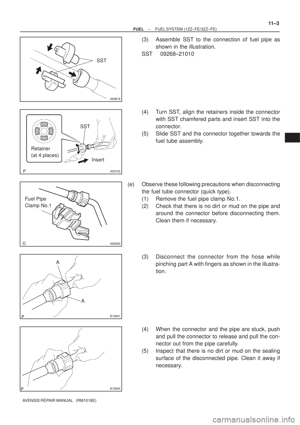
(3) Assemble SST to the connection of fuel pipe as
shown in the illustration.
SST 09268±21010
(4) Turn SST, align the retainers inside the connector
with SST chamfered parts and insert SST into the
connector.
(5) Slide SST and the connector together towards the
fuel tube assembly.
(e) Observe these following precautions when disconnecting
the fuel tube connector (quick type).
(1) Remove the fuel pipe clamp No.1.
(2) Check that there is no dirt or mud on the pipe and
around the connector before disconnecting them.
Clean them if necessary.
(3) Disconnect the connector from the hose while
pinching part A with fingers as shown in the illustra-
tion.
(4) When the connector and the pipe are stuck, push
and pull the connector to release and pull the con-
nector out from the pipe carefully.
(5) Inspect that there is no dirt or mud on the sealing
surface of the disconnected pipe. Clean it away if
necessary.