Page 337 of 1690
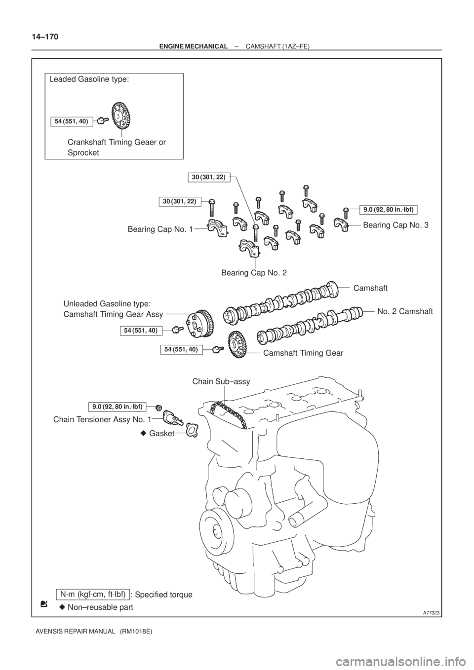
A77323
Leaded Gasoline type:
N´m (kgf´cm, ft´lbf)
: Specified torque
� Non±reusable part
54 (551, 40)
� Gasket
Crankshaft Timing Geaer or
Sprocket
Bearing Cap No. 3
Bearing Cap No. 2
Camshaft
No. 2 Camshaft
Camshaft Timing Gear
Unleaded Gasoline type:
Camshaft Timing Gear Assy
54 (551, 40)
Chain Tensioner Assy No. 1
30 (301, 22)
Bearing Cap No. 1
30 (301, 22)
9.0 (92, 80 in.�lbf)
54 (551, 40)
9.0 (92, 80 in.�lbf)
Chain Sub±assy 14±170
± ENGINE MECHANICALCAMSHAFT (1AZ±FE)
AVENSIS REPAIR MANUAL (RM1018E)
Page 339 of 1690
A77285
Unleaded Gasoline
Leaded GasolineTiming
Marks
Timing
Marks Timing
Marks
Timing
Marks
A77286
Push
A77412
HoldLoosen
A77294
15973
481062 14±172
± ENGINE MECHANICALCAMSHAFT (1AZ±FE)
AVENSIS REPAIR MANUAL (RM1018E)
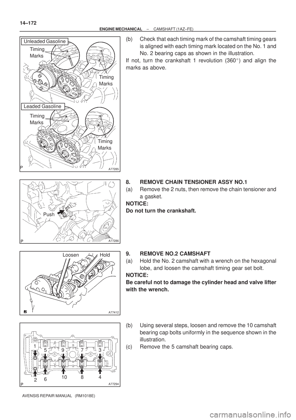
(b) Check that each timing mark of the camshaft timing gears
is aligned with each timing mark located on the No. 1 and
No. 2 bearing caps as shown in the illustration.
If not, turn the crankshaft 1 revolution (360�) and align the
marks as above.
8. REMOVE CHAIN TENSIONER ASSY NO.1
(a) Remove the 2 nuts, then remove the chain tensioner and
a gasket.
NOTICE:
Do not turn the crankshaft.
9. REMOVE NO.2 CAMSHAFT
(a) Hold the No. 2 camshaft with a wrench on the hexagonal
lobe, and loosen the camshaft timing gear set bolt.
NOTICE:
Be careful not to damage the cylinder head and valve lifter
with the wrench.
(b) Using several steps, loosen and remove the 10 camshaft
bearing cap bolts uniformly in the sequence shown in the
illustration.
(c) Remove the 5 camshaft bearing caps.
Page 343 of 1690
A77285
Unleaded Gasoline
Leaded GasolineTiming
Marks
Timing
Marks Timing
Marks
Timing
Marks
A77394
Raise
PinHook Push
A77395
Engine
Front 14±176
± ENGINE MECHANICALCAMSHAFT (1AZ±FE)
AVENSIS REPAIR MANUAL (RM1018E)
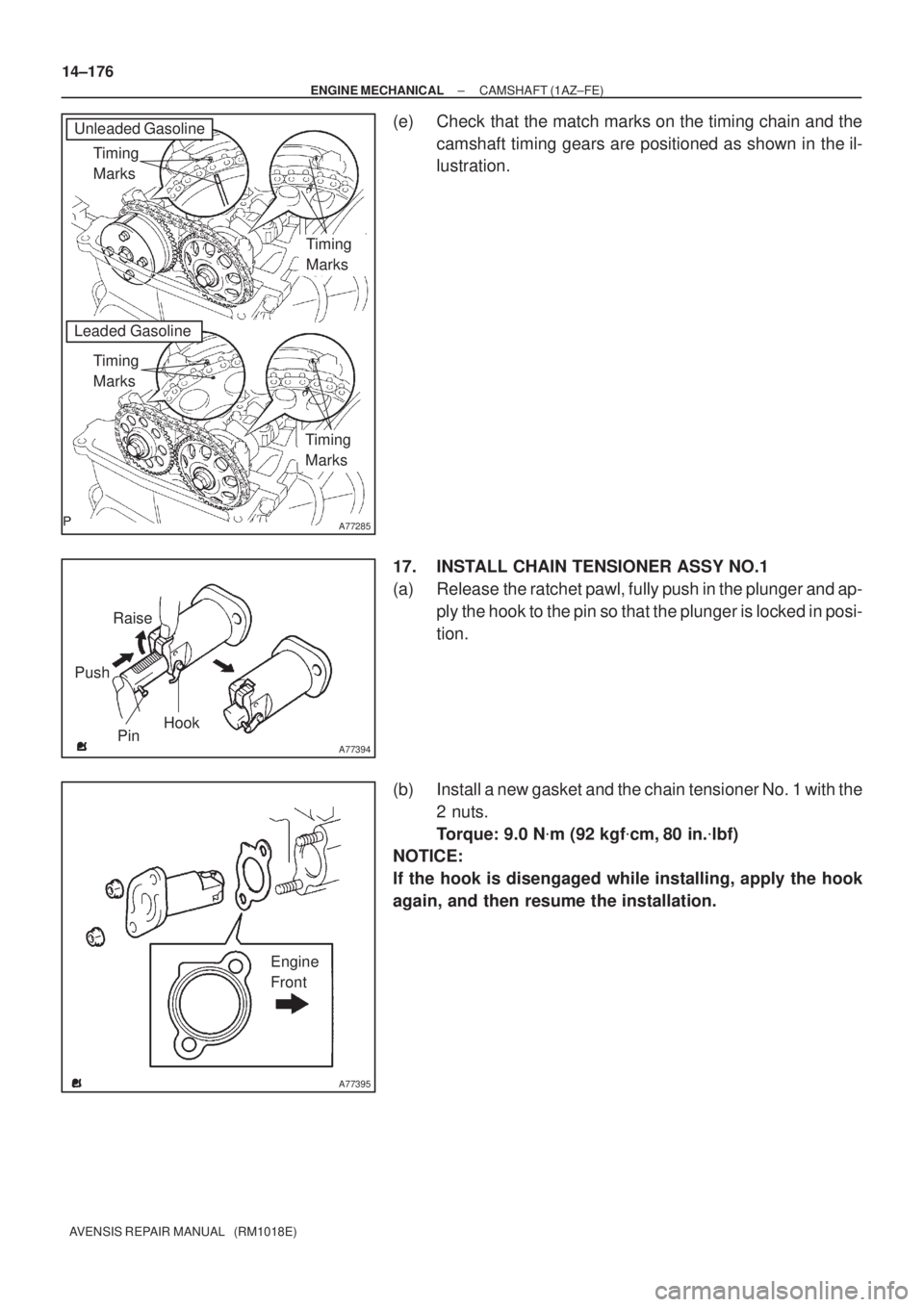
(e) Check that the match marks on the timing chain and the
camshaft timing gears are positioned as shown in the il-
lustration.
17. INSTALL CHAIN TENSIONER ASSY NO.1
(a) Release the ratchet pawl, fully push in the plunger and ap-
ply the hook to the pin so that the plunger is locked in posi-
tion.
(b) Install a new gasket and the chain tensioner No. 1 with the
2 nuts.
Torque: 9.0 N�m (92 kgf�cm, 80 in.�lbf)
NOTICE:
If the hook is disengaged while installing, apply the hook
again, and then resume the installation.
Page 347 of 1690
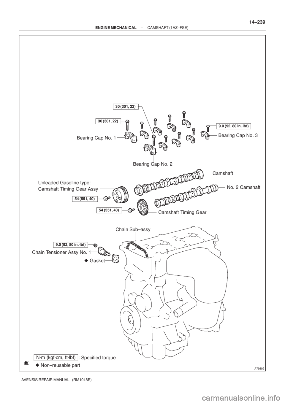
A79802
N´m (kgf´cm, ft´lbf)
: Specified torque
� Non±reusable part� Gasket
Bearing Cap No. 3
Bearing Cap No. 2
Camshaft
No. 2 Camshaft
Camshaft Timing Gear
Unleaded Gasoline type:
Camshaft Timing Gear Assy
54 (551, 40)
Chain Tensioner Assy No. 1
30 (301, 22)
Bearing Cap No. 1
30 (301, 22)
9.0 (92, 80 in.�lbf)
54 (551, 40)
9.0 (92, 80 in.�lbf)
Chain Sub±assy
± ENGINE MECHANICALCAMSHAFT (1AZ±FSE)
14±239
AVENSIS REPAIR MANUAL (RM1018E)
Page 349 of 1690
A77345
Timing
Marks
Timing
Marks
A77286
Push
A77412
HoldLoosen
A77294
15973
481062
A52473
± ENGINE MECHANICALCAMSHAFT (1AZ±FSE)
14±241
AVENSIS REPAIR MANUAL (RM1018E)
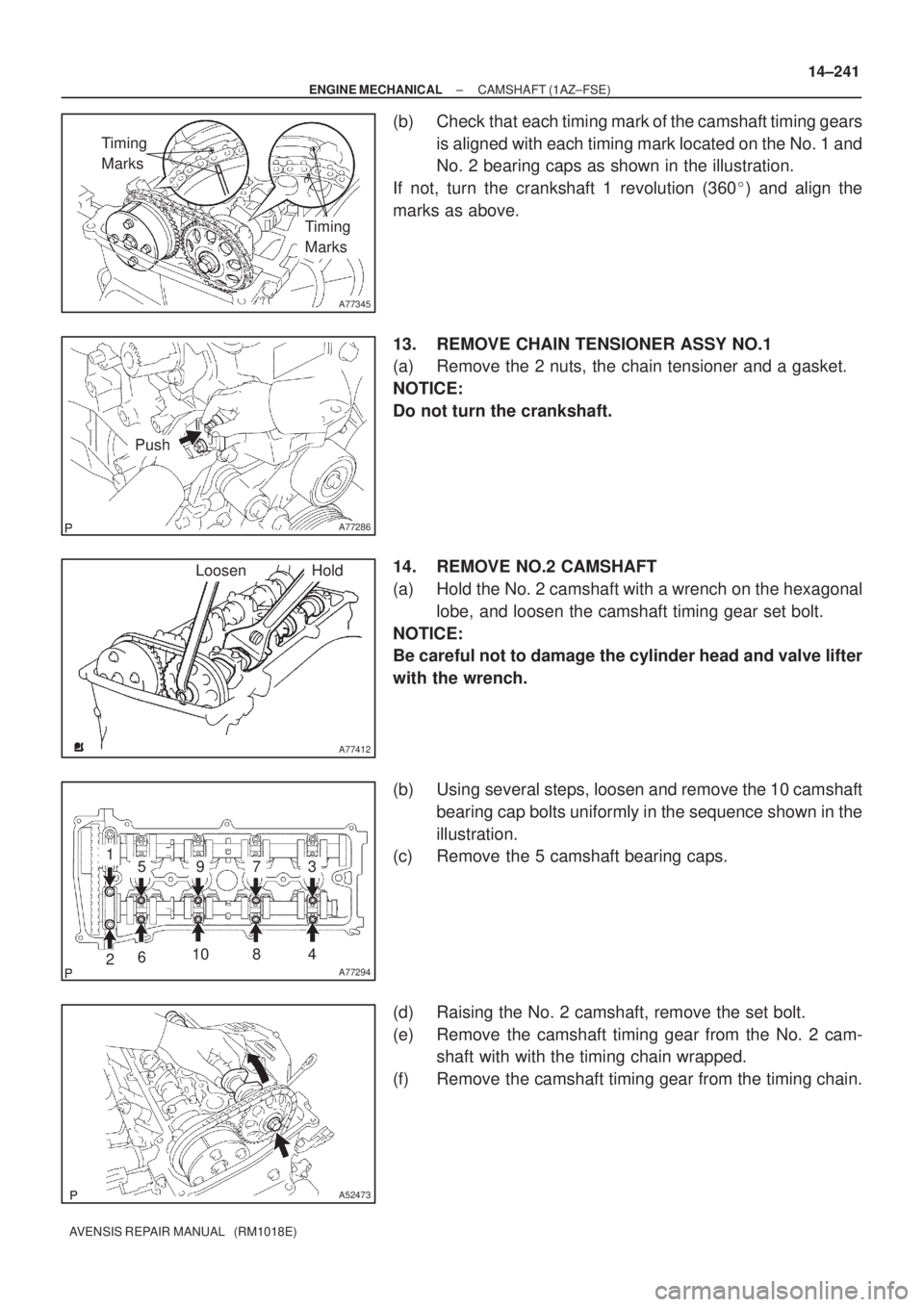
(b) Check that each timing mark of the camshaft timing gears
is aligned with each timing mark located on the No. 1 and
No. 2 bearing caps as shown in the illustration.
If not, turn the crankshaft 1 revolution (360�) and align the
marks as above.
13. REMOVE CHAIN TENSIONER ASSY NO.1
(a) Remove the 2 nuts, the chain tensioner and a gasket.
NOTICE:
Do not turn the crankshaft.
14. REMOVE NO.2 CAMSHAFT
(a) Hold the No. 2 camshaft with a wrench on the hexagonal
lobe, and loosen the camshaft timing gear set bolt.
NOTICE:
Be careful not to damage the cylinder head and valve lifter
with the wrench.
(b) Using several steps, loosen and remove the 10 camshaft
bearing cap bolts uniformly in the sequence shown in the
illustration.
(c) Remove the 5 camshaft bearing caps.
(d) Raising the No. 2 camshaft, remove the set bolt.
(e) Remove the camshaft timing gear from the No. 2 cam-
shaft with with the timing chain wrapped.
(f) Remove the camshaft timing gear from the timing chain.
Page 352 of 1690
A52473
A77416
Bearing Cap No. 2 Bearing Cap No. 3
531 2 4
A77417
TightenHold
A77345
Timing
Marks
Timing
Marks
A77394
Raise
PinHook Push
14±244
± ENGINE MECHANICALCAMSHAFT (1AZ±FSE)
AVENSIS REPAIR MANUAL (RM1018E)
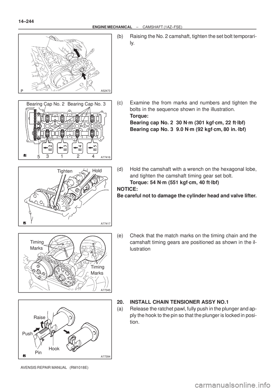
(b) Raising the No. 2 camshaft, tighten the set bolt temporari-
ly.
(c) Examine the from marks and numbers and tighten the
bolts in the sequence shown in the illustration.
Torque:
Bearing cap No. 2 30 N�m (301 kgf�cm, 22 ft�lbf)
Bearing cap No. 3 9.0 N�m (92 kgf�cm, 80 in.�lbf)
(d) Hold the camshaft with a wrench on the hexagonal lobe,
and tighten the camshaft timing gear set bolt.
Torque: 54 N�m (551 kgf�cm, 40 ft�lbf)
NOTICE:
Be careful not to damage the cylinder head and valve lifter.
(e) Check that the match marks on the timing chain and the
camshaft timing gears are positioned as shown in the il-
lustration
20. INSTALL CHAIN TENSIONER ASSY NO.1
(a) Release the ratchet pawl, fully push in the plunger and ap-
ply the hook to the pin so that the plunger is locked in posi-
tion.
Page 353 of 1690
A77395
Engine
Front
A77396
HookPinTurn
Disconnect
A77397
Push Turn
Plunger
±
ENGINE MECHANICAL CAMSHAFT(1AZ±FSE)
14±245
AVENSIS REPAIR MANUAL (RM1018E)
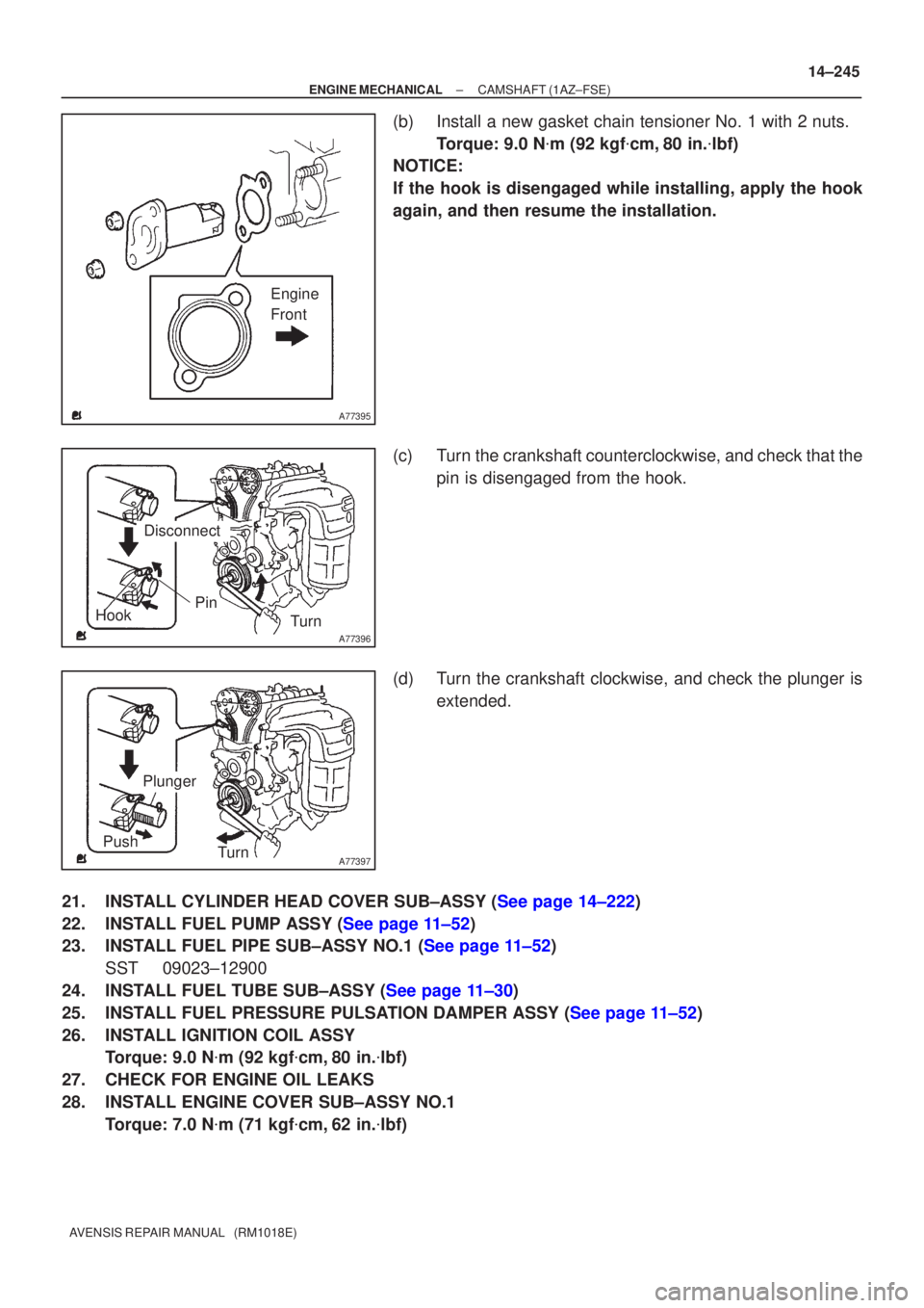
(b)Install a new gasket chain tensioner No. 1 with 2 nuts.
Torque: 9.0 N �m (92 kgf �cm,80 in. �lbf)
NOTICE:
If the hook is disengaged while installing, apply the hook
again, and then resume the installation.
(c)Turn the crankshaft counterclockwise, and check that the
pin is disengaged from the hook.
(d)Turn the crankshaft clockwise, and check the plunger is extended.
21.INSTALL CYLINDER HEAD COVER SUB±ASSY (See page 14±222)
22.INSTALL FUEL PUMP ASSY (See page 11±52)
23.INSTALL FUEL PIPE SUB±ASSY NO.1 (See page 11±52) SST 09023±12900
24.INSTALL FUEL TUBE SUB±ASSY (See page 11±30)
25.INSTALL FUEL PRESSURE PULSATION DAMPER ASSY (See page 11±52)
26. INSTALL IGNITION COIL ASSY Torque: 9.0 N �m (92 kgf �cm, 80 in. �lbf)
27. CHECK FOR ENGINE OIL LEAKS
28. INSTALL ENGINE COVER SUB±ASSY NO.1 Torque: 7.0 N �m (71 kgf �cm, 62 in. �lbf)
Page 356 of 1690
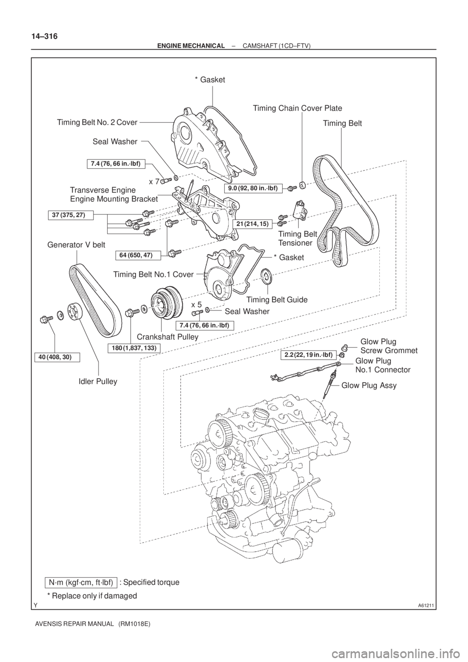
A61211
: Specified torqueN´m (kgf´cm, ft´lbf)
* Replace only if damagedTiming Belt No. 2 Cover
Transverse Engine
Engine Mounting Bracket
Seal Washer Timing Belt No.1 Cover
Crankshaft Pulley Seal Washer
x 5 Generator V belt
Glow Plug
Screw Grommet Timing Belt GuideTiming Belt * Gasket
x 7
Glow Plug Assy * Gasket Timing Chain Cover Plate
Timing Belt
Tensioner
180 (1,837, 133)
21 (214, 15)
9.0 (92, 80 in.´lbf)
37 (375, 27)
64 (650, 47)
2.2 (22, 19 in.´lbf)
7.4 (76, 66 in.´lbf)
7.4 (76, 66 in.´lbf)
Idler Pulley
40 (408, 30)Glow Plug
No.1 Connector
14±316
± ENGINE MECHANICALCAMSHAFT (1CD±FTV)
AVENSIS REPAIR MANUAL (RM1018E)