Page 955 of 1690
B66039
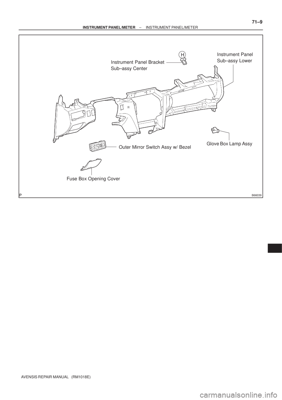
Instrument Panel Bracket
Sub±assy CenterInstrument Panel
Sub±assy Lower
Glove Box Lamp Assy
Outer Mirror Switch Assy w/ Bezel
Fuse Box Opening Cover
H
± INSTRUMENT PANEL/METERINSTRUMENT PANEL/METER
71±9
AVENSIS REPAIR MANUAL (RM1018E)
Page 1025 of 1690
650T5±01
I35250
65±30
±
LIGHTING HEADLAMP LEVELING ECU ASSY
AVENSIS REPAIR MANUAL (RM1018E)
HEADLAMP LEVELING ECU ASSY
REPLACEMENT
1. REMOVE GLOVE COMPARTMENT DOOR ASSY (LHD STEERING POSITION TYPE) (See page 71±11)
2.REMOVE FUSE BOX OPENING COVER (RHD STEERING POSITION TYPE) (See page 71±11)
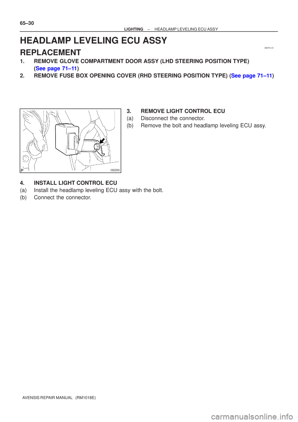
3. REMOVE LIGHT CONTROL ECU
(a) Disconnect the connector.
(b) Remove the bolt and headlamp leveling ECU assy.
4. INSTALL LIGHT CONTROL ECU
(a) Install the headlamp leveling ECU assy with the bolt.
(b) Connect the connector.
Page 1428 of 1690
190NV±01
19±14
± STARTING & CHARGINGCHARGING SYSTEM (1AZ±FE)
AVENSIS REPAIR MANUAL (RM1018E)
CHARGING SYSTEM (1AZ±FE)
PRECAUTION
1. Check that the battery cables are connected to the correct terminals.
2. Disconnect the battery cables when the battery is given a quick charge.
3. Do not perform tests with a high voltage insulation resistance tester.
4. Never disconnect the battery while the engine is running.
5. Check that the charging cable is tightened on terminal B of the generator and the fuse box.
Page 1431 of 1690
190NS±01
± STARTING & CHARGINGCHARGING SYSTEM (1AZ±FSE)
19±17
AVENSIS REPAIR MANUAL (RM1018E)
CHARGING SYSTEM (1AZ±FSE)
PRECAUTION
1. Check that the battery cables are connected to the correct terminals.
2. Disconnect the battery cables when the battery is given a quick charge.
3. Do not perform tests with a high voltage insulation resistance tester.
4. Never disconnect the battery while the engine is running.
5. Check that the charging cable is tightened on terminal B of the generator and the fuse box.
Page 1434 of 1690
190NM±01
± STARTING & CHARGINGCHARGING SYSTEM (1CD±FTV)
19±25
AVENSIS REPAIR MANUAL (RM1018E)
CHARGING SYSTEM (1CD±FTV)
PRECAUTION
1. Check that the battery cables are connected to the correct terminals.
2. Disconnect the battery cables when the battery is given a quick charge.
3. Do not perform tests with a high voltage insulation resistance tester.
4. Never disconnect the battery while the engine is running.
5. Check that the charging cable is tightened on terminal B of the generator and the fuse box.
Page 1438 of 1690
190NP±01
19±4
± STARTING & CHARGINGCHARGING SYSTEM (1ZZ±FE/3ZZ±FE)
AVENSIS REPAIR MANUAL (RM1018E)
CHARGING SYSTEM (1ZZ±FE/3ZZ±FE)
PRECAUTION
1. Check that the battery cables are connected to the correct terminals.
2. Disconnect the battery cables when the battery is given a quick charge.
3. Do not perform tests with a high voltage insulation resistance tester.
4. Never disconnect the battery while the engine is running.
5. Check that the charging cable is tightened on terminal B of the generator and the fuse box.