I35431
Burner Motor
Glow Plug
Surface Sensor
Temp. Control Sensor
Flame Sensor13
Power
Heater
ECU
Connector BTerminal L
of AlternatorBattery
Metering Pump
Fuse (20 A)
Vehicle Side SW 14
9
12
5
6
3
4
1
2R
BR
B±R
G
L±Y
L
Y
L±W5
1
6
2
7
3
8
4W±B
R±G
R±B Connector A
IG
W±R (*1)
Y±R (*2)
R±L (*1)
R±Y (*2)
*1: TMC Made
*2: TMUK Made 55±16
± HEATER & AIR CONDITIONERCOMBUSTION TYPE POWER HEATER SYSTEM
AVENSIS REPAIR MANUAL (RM1018E)
2. DESCRIPTION OF DISPLAY AND BUTTONS
(a) AF: Current Value Malfunction (Blinking at current failure)
Diag: DTC (Example: 064 Flame sensor break)
Memory Clear button: Deletion of faulty memory (Press both buttons together for longer than 2 se-
conds)
> Button: Scroll up of faulty memory (The past 5 codes can be stored.)
< Button: Scroll down of faulty memory (The past 5 codes can be stored.)
3. FAULTY MEMORY
(a) The ECU is able to store up to 5 pieces of faulty memory. If it is full, the new data is written over F5.
4. WIRING DIAGRAM
SFI
SFISFI
SFISFI
SFI
D25842
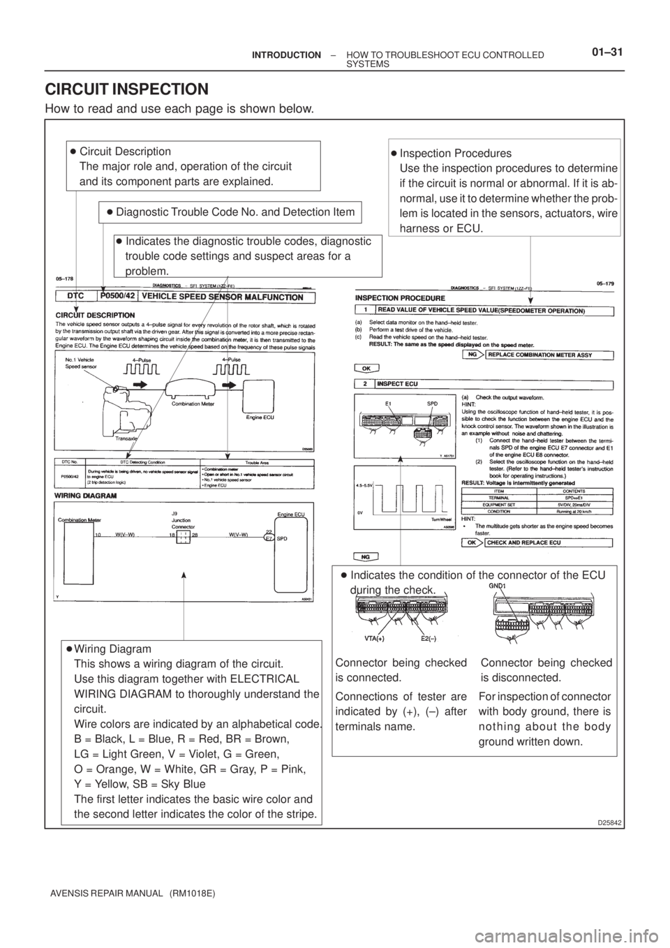
� Circuit Description
The major role and, operation of the circuit
and its component parts are explained.
� Diagnostic Trouble Code No. and Detection Item
� Indicates the diagnostic trouble codes, diagnostic
trouble code settings and suspect areas for a
problem.
Wiring Diagram
This shows a wiring diagram of the circuit.
Use this diagram together with ELECTRICAL
WIRING DIAGRAM to thoroughly understand the
circuit.
Wire colors are indicated by an alphabetical code.
B = Black, L = Blue, R = Red, BR = Brown,
LG = Light Green, V = Violet, G = Green,
O = Orange, W = White, GR = Gray, P = Pink,
Y = Yellow, SB = Sky Blue
The first letter indicates the basic wire color and
the second letter indicates the color of the stripe.�Inspection Procedures
Use the inspection procedures to determine
if the circuit is normal or abnormal. If it is ab-
normal, use it to determine whether the prob-
lem is located in the sensors, actuators, wire
harness or ECU.
� Indicates the condition of the connector of the ECU
during the check.
�
Connections of tester are
indicated by (+), (±) after
terminals name.
Connector being checked
is connected.Connector being checked
is disconnected.
For inspection of connector
with body ground, there is
nothing about the body
ground written down.
± INTRODUCTIONHOW TO TROUBLESHOOT ECU CONTROLLED
SYSTEMS01±31
AVENSIS REPAIR MANUAL (RM1018E)
CIRCUIT INSPECTION
How to read and use each page is shown below.

Vehicle Side SW 14
9
12
5
6
3
4
1")